Gallery opened Jan 2003
Updated: 16 Feb 2014
More on the NYC HS-1a loco
Hello to Robert Hord Jr, who inspired this page.


American High-Pressure Locomotives |
Gallery opened Jan 2003 |
|
THE BALDWIN 60000
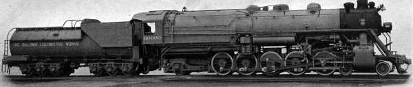 | Left: Baldwin No. 60000 of 1926.
|
The watertube boiler generated steam at 350 psi, feeding the central HP cylinder, which fed the two outer LP cylinders. All three cylinders were the same size, which gave good load-balancing between the cylinders and gave vibration-free running under test at the Pennsylvania Railroad's test facility in Altoona. Using cutoffs of 50 to 90% on the HP cylinder, and 20 to 70% on the LP cylinders, between 1500 and 4515 horsepower could be obtained, the latter being the limit of the test facility; this had never been reached before. Walschaerts valvegear was fitted. The tender had two six-wheeled trucks, and carried 12,000 gallons of water and 16 tons of coal.
The 60000 then embarked on an ambitious program as a demonstrator, eventually covering 100,000 miles. It began by working on the Pennsylvania Railroad between Enola and West Morrisville, where it proved it could haul a 7000-ton train up a 26-mile long incline. It then went to Chicago, where it was displayed to more than 20,000 spectataors, and then worked on Southern Illinois coal trains, then moving to the Atchison, Topeka & Santa Fe Railroad at Fort Madison. Dynamometer tests on the same line between Clovis and Belen, New Mexico, showed that the 60000 used between 20 and 25% less fuel and water than the 3800-series 2-10-2's of the AT&SF. The 60000 was then converted to oil-firing at Sacremento and worked on the Southern Pacific Railroad; it was reconverted to coal at Minot, North Dakota, and ran back via Chicago to Philadephia in 1927. The 60000 received glowing reports as it proceeded on this odyssey, and Baldwin waited for the orders to roll in, being so confident that they began to order materials for the water-tube fireboxes.
But the orders never came. J Parker Lamb in Perfecting the American Steam Locomotive attributes this partly to conservatism on the part of railway operators, who were wary of the radical change involved in a water-tube firebox working at 350 psi. There was a particular suspicion that cleaning scale out of the water tubes would be difficult and costly, and a general feeling that the economies gained by high-pressure and compounding would be more than cancelled by higher maintenance costs and poor reliability. The axle loadings on the drivers were also too great for any but the heaviest of track.
The 60000 was eventually put to use as a stationary power source at Baldwin's Pennsylvania works.
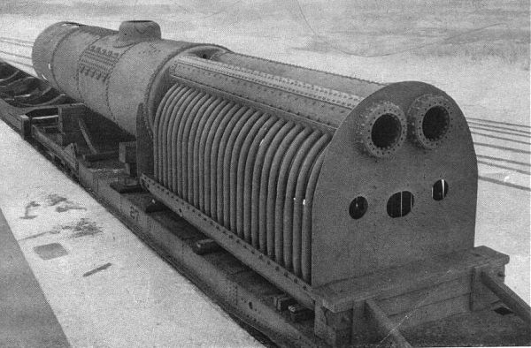 | Left: The boiler of No. 60000
|
Uniquely among the locomotives on this page, the 60000 still survives. In 1933 it was installed in the Franklin Institute Science Museum in Philadelphia, Pennsylvania, where it still remains.
 | Left: No. 60000 in the Franklin Institute
|
DATA FOR THE 60000
Boiler pressure: 	350 psi
HP Cylinder: 		27x32 inches
LP Cylinders: 		27x32 inches
Boiler diameter: 	84 inches
Driver diameter: 	63.5 inches
Weight on drivers: 	338,400 lbs
Total engine weight: 	457,500 lbs
Total weight: 		700,900 lbs
Tractive effort: 	 82,500 lbs
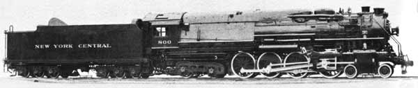 | Left: The NYC HS-1a of 1931. No.800
|
The HS-1a used the Schmidt High-pressure System, in which a sealed (and hence scale-free) ultra-high-pressure steam circuit transferred heat to a high-pressure boiler, by means of heating coils inside it. The hot gases from the HP boiler were then passed through a conventional fire-tube low pressure boiler.
The HP boiler generated steam at 850 psi, feeding the central cylinder. The LP boiler generated steam at 250 psi and fed the two outer cylinders.
| Information on the NYC HS-1a is very scarce. There is no Wikipedia entry.
|
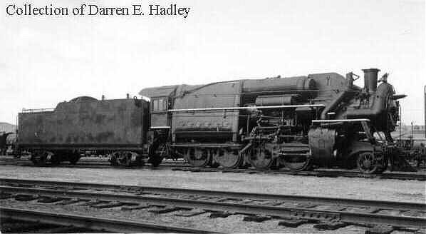
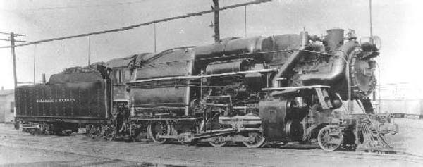 | Left: No 1400 2-8-0 'Horatio Allen'
|
| The most unusual feature of the Horatio Allen was its high operating pressure, made possible by the use of the Muhlfeld watertube boiler. The boiler barrel was conventional with fire tubes and a superheater, but the firebox was enclosed by four steam drums, two at the top and two at the bottom, with five vertical watertubes connecting the top and bottom drums at each side of the firebox. The bottom drums extended only for the length of the firebox, but the top steam drums extended farther forward, over the boiler barrel. There was no transverse tube connection between the two top drumsAnother unusual feature was the use of Young valve gear. This gear can provide a maximum cutoff of greater than 90%, whereas most valve gears can only give up to 85% cutoff. The Horatio Allen was said to have given good fuel economy, but required a lot of maintenance. |
 | Left: Side view of No 1400 'Horatio Allen' |
 | Left: Another view of No 1400
|
 | Left: The boiler of No 1400
|
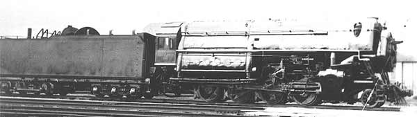 | Left: No 1401 John B Jervis 2-8-0
Boiler pressure was higher at 400 psi, and the cylinders were slightly smaller. |
 | Left: The John B Jervis in 1927
|
 | Left: The John B Jervis again.
|
 | Left: No 1402 2-8-0 "James Archbald"
|
By 1935, #1400, #1401 and #1402 were out of use and in storage in Oneonta. Their maintenance had proved burdensome and they were also victims of a general change in American locomotive policy. The "superpower" era brought with it the concept that it was better to pull lighter (though still very heavy) loads at faster speeds. On the D&H this led to high-speed 4-8-4s and Mallet 4-6-6-4s.
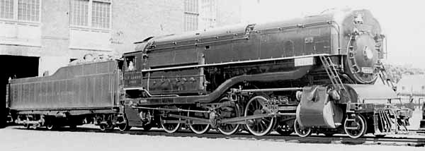
THE L F LOREE TRIPLE EXPANSION LOCOMOTIVE No.1403
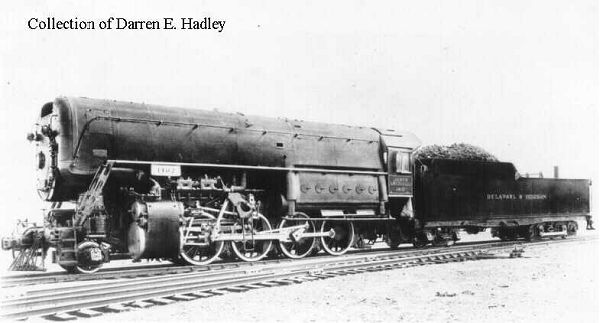
 | Left: The L F Loree 4-8-0 locomotive at the Century of Progress Exposition, held in Chicago in 1933.
It was a remarkable triple-expansion engine with a water-tube boiler. Sadly it was not sucessful. |
Picture above by Cecil Wickham. Used by courtesy of Dr Richard Leonard, whose Steam Locomotive Archive site can be seen at www.railarchive.net. His page on the L F Loree is at www.railarchive.net/centprog/lf_loree.htm.
The boiler was a water-tube design working at 500 psi, the steam feeding an HP cylinder under the right side of the cab, then an intermediate-pressure (acronym IP or MP to taste) cylinder under the left of the cab, and finally the two LP cylinders at the front. Both front and rear cylinders acted on the second driving axle. The LP exhaust went out through the chimney blastpipe as usual. Dabeg poppet valves were fitted, driven by rotary cams.
The rear of the tender was carried by a 6-wheel Bethlehem "Auxiliary Locomotive" (or booster), which operated at the full boiler pressure of 500 psi to give extra effort for starting.
The locomotive was named after L F Loree, who was the D&H president from 1907 to 1938. He is credited with originating the phrase "This is a helluva way to run a railroad!".
Regrettably the L F Loree proved unreliable- one long-suffering D&H employee is recorded as saying "Every time we sent her out a machine shop had to go with her".
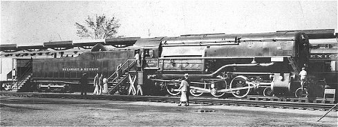
 | Left: Another view of the L F Loree 4-8-0.
|
DATA FOR THE L F LOREE
     Configuration. . . . . . . . . . . . . . .       4-8-0
     Weight on engine truck, pounds . . . . . .      69,000
     Weight on drivers, pounds  . . . . . . .       313,000
     Weight of engine, pounds . . . . . . . .       382,000
     Weight of tender loaded, pounds  . . . .       287,000
     Weight of engine and tender, pounds . . .      669,000

     Boiler pressure, psi . . . . . . . . .             500
                {1 High pressure . . . . . .      20" x 32"
     Cylinders  {1 Intermediate pressure         27.5"x 32"
                {2 Low pressure . . . . . .       33" x 32"
     Driver diameter . . . . . . . . . . . .            63"

     Tractive effort, triple, pounds . . . . .       75,000
     Tractive effort, simple, pounds . . . . . . .   90,000
     Tractive effort, auxiliary locomotive, pounds . 18,000
     Tractive effort, maximum, pounds . . . .       108,000
     Grate area, square feet . . . . . . . . . .       75.8

     Valves and motion . . . .           Poppet, Rotary Cam
     Feed water heater . . . . . . . . . .            Dabeg
     Tank capacity . . . . . .    14,000 Gallons, 17.5 Tons
     Fuel. . . . . . . . . . . . . . .      Bituminous coal
     Track gauge . . . . . . . . . . . . .           4' 8.5"
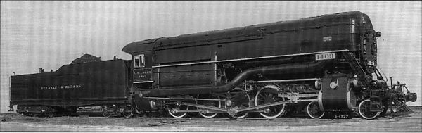 | Left: Another picture of the L F Loree.
|
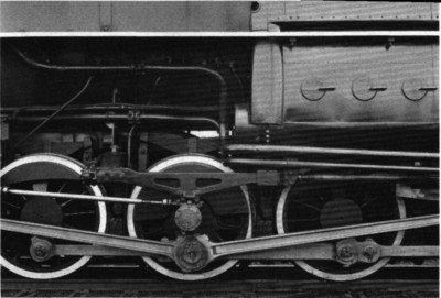 | Left: The second driving wheel, with its two connecting rods.
|
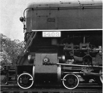 | Left: The front end of the L F Loree.
|

|