Long ago, when the world was a more innocent place than it is now, my mother would take me with her to a large department store- I think it was the Co-op.
When you bought something, the sales assistant would take the money and the paperwork, stuff it into a small metal cylinder, and offer it to the mouth of a large bronze pipe. This pipe inhaled it with a great rush of air, and a minute or two later the change and receipt would appear in another cylinder disgorged from an adjacent bit of pipework, having been dispensed by a cashier safely tucked away from the rigours of armed robbery. I was fascinated. It was a pneumatic message system.
While many small systems were built for use only in one building or by one enterprise, there were also large public networks constructed by national post offices, usually in the capital cities. Perhaps surprisingly, these pneumatic systems were built long after electrical telegraphy had become established. One motivation was that telegraphists were skilled workers, and had to be paid accordingly. Pushing a carrier into a pipe requires much less skill.
This technology is still alive in some applications- it can deliver physical objects, which is hard to do with email. Obviously there are limitations. A transatlantic system might present a few engineering challenges...
HOW IT WORKS
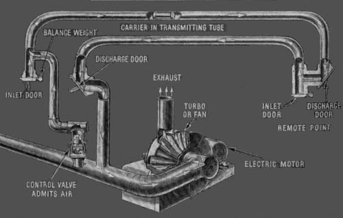 |
| Left: the basics of pneumatic messaging
The central exhauster sucks the message carriers through the pipes.
In this case the whole system is at below atmospheric pressure, so a carrier can be sent on its way simply by pushing it into a tube. More sophisticated sytems used both pressure and vacuum to move carriers; see the work of Varley in PNEUMATIC DESPATCH IN GREAT BRITAIN.
|
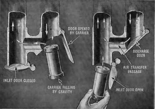 |
| Left: on the left a carrier arrives
Its momentum and weight push open the discharge door, the carrier drops out, and air pressure closes the door again. On the right, a carrier is sent by pulling open the inlet door and allowing the carrier to be sucked in. The inlet door is then closed by its counterweight.
Note that the carrier is wider at its ends, to prevent the central part binding against the tube wall in curves.
|

EARLY HISTORY
The first known work on pneumatic transport was done by the Englishman George Medhurst (1759-1827). During a period of a few years about 1810, he invented not only the pneumatic dispatch tube, but also the pneumatic railway, which is somewhat outside the scope of this page. Medhurst's invention pushed a capsule along a tube a few inches in diameter, using positive air pressure; thus was born the pneumatic dispatch tube.
In 1853 J. Latimer Clark installed a 220 yard pneumatic tube between the London Stock Exchange in Threadneedle Street and the Central Station of the Electric Telegraph Company in Lothbury. The Electric Telegraph Co had been up and running long before pneumatics came along; the company was incorporated in 1846. There were similar installations in Berlin (1865) between the Central Telegraph Office and the Stock Exchange, and in Paris (1866) to the Place de La Bourse. Of these, more later. It is important to remember that the pneumatic system was not a crude and early forerunner of the electric telegraph, but came after it; Cooke and Wheatstone opened the world's first commercial telegraph between Paddington and West Drayton, a distance of 13 miles, in 1838.
The various networks are described below in the order of the opening.
PNEUMATIC DESPATCH IN GREAT BRITAIN: OPENED 1853.
This is an edited and revised version of the information contained in the article on "Pneumatic Despatch" in the 1911 edition of Encyclopaedia Brittanica.
"Pneumatic Despatch is the name given to the transport of written despatches through tubes by the agency of air pressure. It was introduced in 1853 by J Latimer Clark, between the Central and Stock Exchange stations of the Electric and International Telegraph Company in London. These stations were connected by a tube 1.5 inches in diameter and 220 yards long. Carriers containing batches of telegrams, and fitting piston-wise in the tube, were sucked through it (in one direction only) by the production of a partial vacuum at one end. In 1858 C F Varley improved the system by using compressed air to force the carriers in one direction, a partial vacuum being still used to draw them in the other direction. This improvement enables single radiating lines of pipe to be used both for sending and for receiving telegrams between a central station supplied with pumping machinery and outlying stations not so supplied."
"In the hands of R S Culley and R Sabine the radial system of pneumatic despatch was in 1870 brought to great perfection in connection with the telegraphic department of the British post office, since that date the total length of tubes (which are employed for telegrams only) has been greatly increased. In 1909 there was in London a total length of 40 miles, whilst in all large and also in very many smaller provincial towns there are installations; these are constantly being added to, as it is found more economical to transmit local message-work by tube rather than by wire, as skilled telegraphists are not required, but only tube attendants.
In some cases only a single tube is necessary, but three or four, or even more, are in use in some towns, according to local circumstances. Short tubes, known as house tubes are in use in a great number of offices; such tubes, which are worked either by handpumps (when the tubes are very short and the traffic light) or by power, are usually 1.75 in. in diameter, and are used for the purpose of conveying messages from one part of a telegraph instrument-room to another, or from the instrument-room to the public counter."
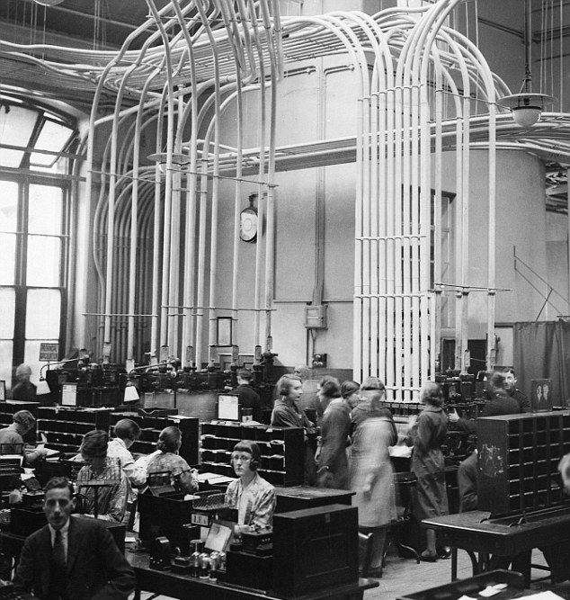 |
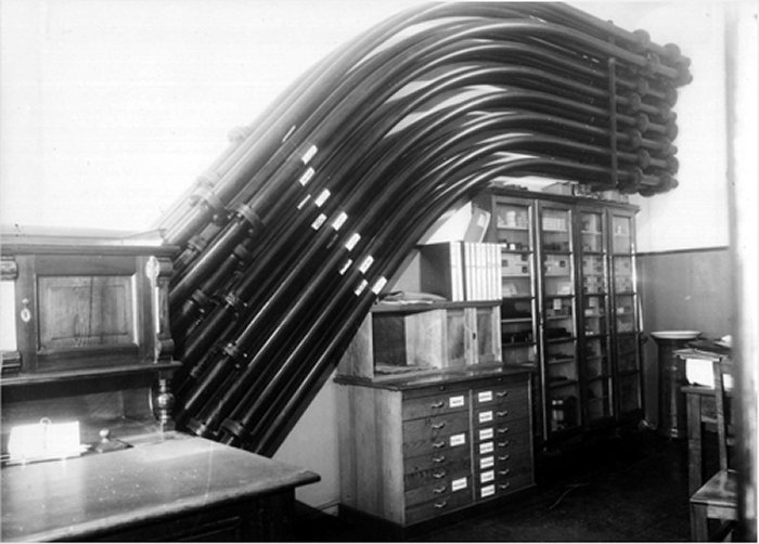
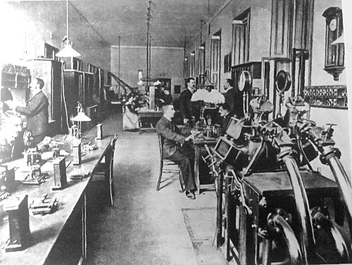
| Left: The Central Telegraph Office of the GPO in London, Oct 1932, showing an impressive pneumatic installation. Communications were still labour-intensive; there were 3000 employees.
The tubes were used to send telegraph forms from local post-offices to the Central Telegraph Office, where the skilled telegraph operators were concentrated.
|
"The underground, or street tubes are mostly 2.75 in. in diameter, but there are also a number of 3-in, tubes in use; those in the large provincial towns (Birmingham, Bradford, Cardiff, Edinburgh, Glasgow, Grimsby, Liverpool, Manchester, Newport, Leeds, Newcastle, Southampton and Swansea) are 2.75 in. in diameter; but in Dublin, Gloucester, Lowestoft and Milford 1.75-in. tubes are employed. There are fifty street tubes in London, varying in length from 100 to 2000 yards. (Central Office to the Houses of Parliament), and also seventy-five house tubes; the pumps for the whole system are worked by four 100 horse-power steam-engines.
At Cardiff, Edinburgh, Gloucester, Leeds, Lowestoft, Newport, Southampton and Swansea the air-pumps are driven by electric motors; at Bradford and Grimsby gas engines are used, and at Milford an oil-engine.
"The tubes are in all cases of lead, the 2.75-in, tubes weighing 8 lb/foot, and being made in lengths of 28 ft; they are enclosed in 3-in, cast-iron pipes made in lengths of 9 ft.
Great care is exercised in making the joints in the lead pipes. Before the tube is placed in its trench a strong chain is passed through it, and a polished steel mandrel, 6 in. long and slightly less in diameter than the diameter of the tube, is heated and attached to the chain, and pushed half its length into the end of the tube already laid; the new length of tube is then forced over the projecting end of the mandrel until the tube ends (which have been previously cut flat) butt perfectly together; an ordinary plumbers joint is then made. By this means the tube is made perfectly air-tight, and the mandrel keeps the surface of the tube under the joint as smooth as at any other part of its length. After the joint is completed the mandrel is drawn out by the chain attached to it, the next length is drawn on, and the above process repeated. The tubes are laid about 2 ft. below the surface of the ground."
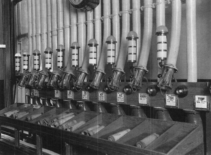 |
| Left: A tube drop point at the Central Telegraph Office in the 1930s
|
"The tubes radiate from the central to the branch offices, the principal offices having two tubes, one for inward and the other for outward traffic. At the smaller offices both the inward and the outward traffic is carried on through one tube. The carriers are made with guttapercha bodies, covered with felt, the front of the carrier being provided with a buffer or piston formed of several disks of felt which closely fit the tube; the messages are prevented from getting out of the carrier by the end being closed by an elastic band, which can be stretched sufficiently to allow the message forms to be inserted. The 3-in. carriers will hold 75 ordinary message forms, the 2.75-in, carriers hold 25 forms, and the 1.5-in. carriers 20 forms. The carriers are propelled from the central office by pressure, and drawn in the opposite direction by vacuum, the standard pressure and vacuum being 10 psi and 6.75 psi respectively, which values give approximately the same speed."
"For a given transit time the actual horse-power required is much less in the case of vacuum than in the case of pressure working, owing to the density of the air column moved being much less:
thus, for example, the transit time for 10 lb pressure is the same as for 6.75 lb vacuum, but the horse-power required in the two cases is as 1.83 to 1. A tube 1 mile long, 2.75 in. in diameter, and worked at 10 lb per square inch pressure, will have a transit time of 2.75 minutes, and will theoretically require 335 horse-power to be expended in working it, (Editor's Note: I think this must be a misprint, as it seems a quite excessive amount of power) although actually 25% more horse-power than this must be allowed for, owing to losses through various causes. The transit time for a 2.75-in, tube is 16% more than for a 3-in, tube of the same length, when both are worked at the same pressure, but the horse-power required is 50 % less; it is not advisable, therefore, to use a tube larger than is absolutely necessary to carry the volume of traffic required."
"The somewhat complicated pattern of double sluice valve originally used at the central stations has been superseded by a simpler form, known as the D box, so named Despatching from the shape of its cross section. This box is of and cast iron, and is provided with a close-fitting, Receiving brass-framed, sliding lid with a glass panel. This Apparatus, lid fits air-tight, and closes the box after a carrier has been inserted into the mouth of the tube; the latter enters at one end of the box and is there bell-mouthed. A supply pipe, to which is connected a 3-way cock, is joined on to the box and allows communication at will with either the pressure or vacuum mains, so that the apparatus becomes available for either sending (by pressure) or receiving (by vacuum) a carrier. Automatic working, by which the air supply is automatically turned on on the introduction of the carrier into a tube and on closing of the D box, and is cut off when the carrier arrives, was introduced in 1909."
"On the long tubes (over about 1000 yds) a modification of the D box in its simplest form is necessary; this modification consists in the addition of a sluice valve placed at a distance of about 9 in. (i.e. rather more than the length of a carrier) from the mouth of the tube. The sluice valve, by means of an interlocking arrangement, is so connected with the sliding lid of the box that the lid cannot be moved to the open position unless the sluice valve has closed the tube, nor can. the sluice valve be opened unless the sliding lid is closed. The object of this sluice valve is to prevent the back rush of air which would take place into the tube when the sliding lid is opened to take out a carrier immediately on the arrival of the latter; for although the vacuum may be turned off by the 3-way cock, yet, owing to the great length of the tube, equilibrium does not immediately take place in. the latter, and the back rush of air into the vacuum when the lid is opened to extract the carrier will cause the latter to be driven back into the tube. The sluice also prevents a similar, but reverse, action from taking place when pressure working is being carried on."
"As a rule, only one carrier is despatched at a time, and the second carrier is inserted in the tube until the arrival of the first one at the farther end is automatically signalled (by an electric apparatus) to the despatching office. On some of the long tubes a carrier, when it passes the midway point in the tube, strikes a trigger and sends back an electrical signal indicating its passage; on the receipt of this signal a second carrier may be despatched. This arrangement has been almost entirely superseded by a signalling apparatus which by a clock movement actuates an indicating hand and moves the latter to tube clear a certain definite time (30 to 40 seconds) after a carrier has beer inserted in the tube. By this arrangement carriers can be despatched one after the other at comparatively short interval~ of time, so that several carriers (separated by distinct intervals may be travelling through the tube simultaneously. It is necessary that the carriers be separated by a definite interval otherwise they tend impact each another and may become jammed."
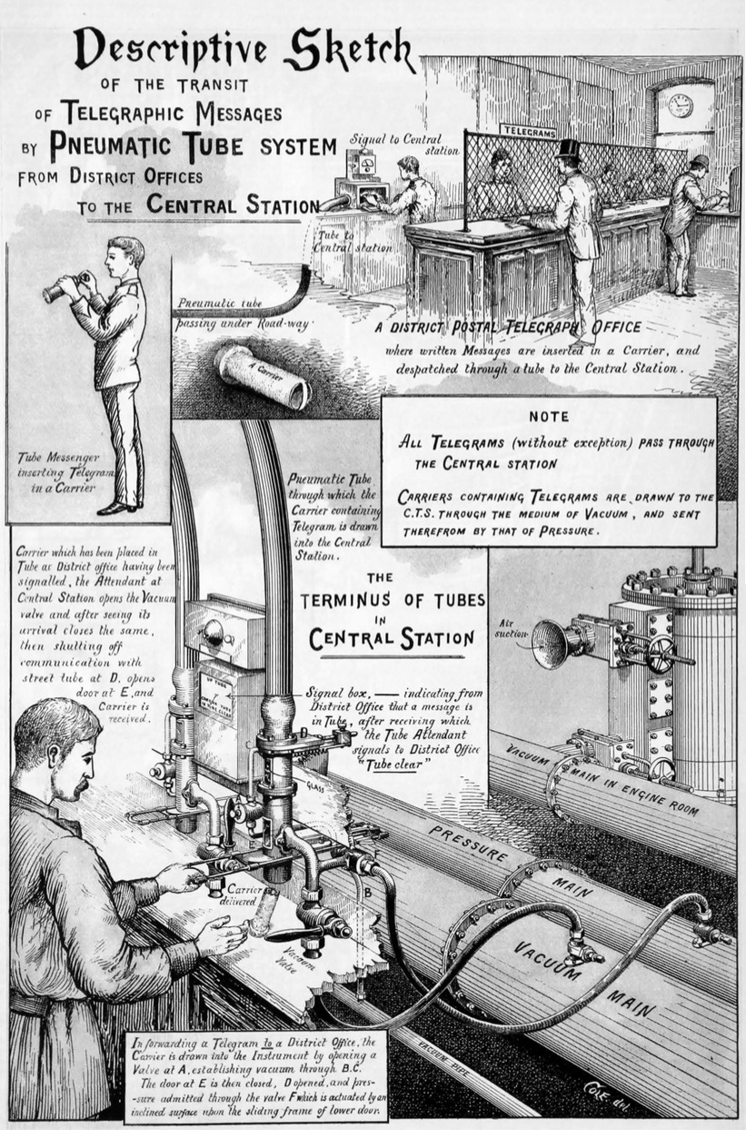 |
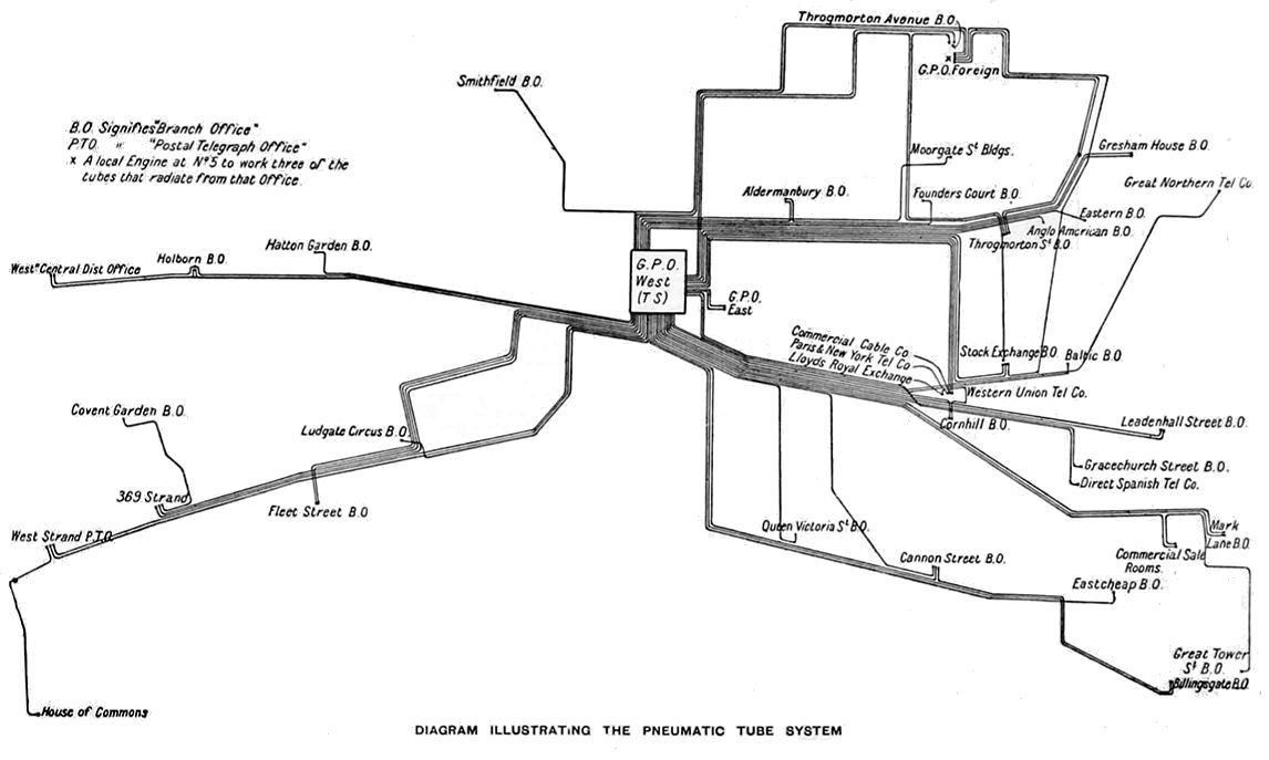
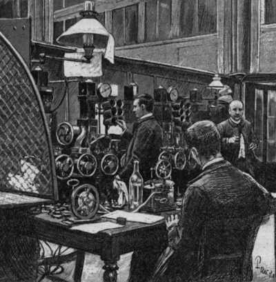
| Left: How the London system worked
It is interesting to see that the system wholly depends on the use of the electric telegraph so the sender can tell the receiver a carrier is on the way, and so the receiver can tell the sender is carrier has arrived. This corresponds with the absolute block method of railway signalling, in which only one train is permitted in a block. It does not correspond with the methods described above; the clock method is equivalent to the time-interval system of train signalling, which caused many accidents and was eventually abandoned.
At bottom right a man at the central station is receiving a carrier drawn to the station by the vacuum. It is not currently clear why there is both a vacuum main and a much smaller vacuum pipe; possibly the 'pipe' carried less vacuum so carriers would not be sucked too violently into the apparatus, endangering the operator's fingers.
The original source of this fine drawing has now been identified as The Engineer, for 18th December 1899. Info courtesy of Tom Bates.
|
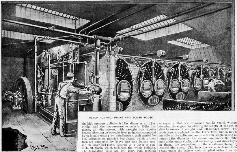 |
| Left: The boilers at the General Post Office: 1899
Six double-furnace Cornish multi-tubular boilers are shown here. Each has a large weight poised above it, which presumably weighted the safety valve. The boilers were 6ft 6in in diameter and 20ft 2in long, with two flues 2ft 6in in diameter and 14ft 6in long, terminating in 74 tubes 3in diameter and 5ft 9in long.
Each boiler is fitted with a single water-gauge (locomotive practice was to have two) a pressure-gauge and a clack-valve for boiler feed at the bottom of the vertical pipe. The valves with their handles tilted downwards are presumably the steam stop valves for each boiler.
At the left is shown one of two 15HP beam-engines for feeding water to the boilers. The bevel gearing at extreme left drove two three-throw pumps which drew water from a well, hinted at in the bottom left corner.
The text gives some details of the main steam engines.
Image from The Engineer, for 18th December 1899, courtesy of Tom Bates.
|
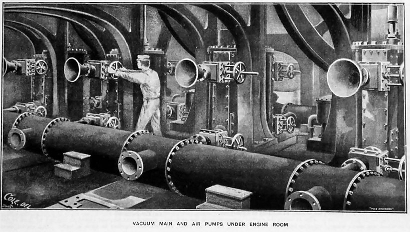 |
| Left: Vacuum and pressure pumps at the General Post Office: 1899
The vacuum and pressure pumps were installed in the basement, underneath the steam engines that drove them. Each pump could either draw from an 18-inch vacuum main, or force air into two 15-inch pressure mains, depending on the setting of the valves shown on the sides of the pump cylinders. The general air of steampunk nightmare is augmented by the menacing-looking horns; these were actually entry diffusers to reduce losses when the pumps sucked in atmospheric air. The handwheels, one of which is being clutched by an intrepid worker, determined if the flow of air was from atmosphere to the pressure main, or from the vacuum main to the pressure main.
This picture (probably drawn from a photograph) shows the nearest main to not be in use as its branches are unconnected to anything and not blanked off.
Image from The Engineer, for 18th December 1899, courtesy of Tom Bates.
|
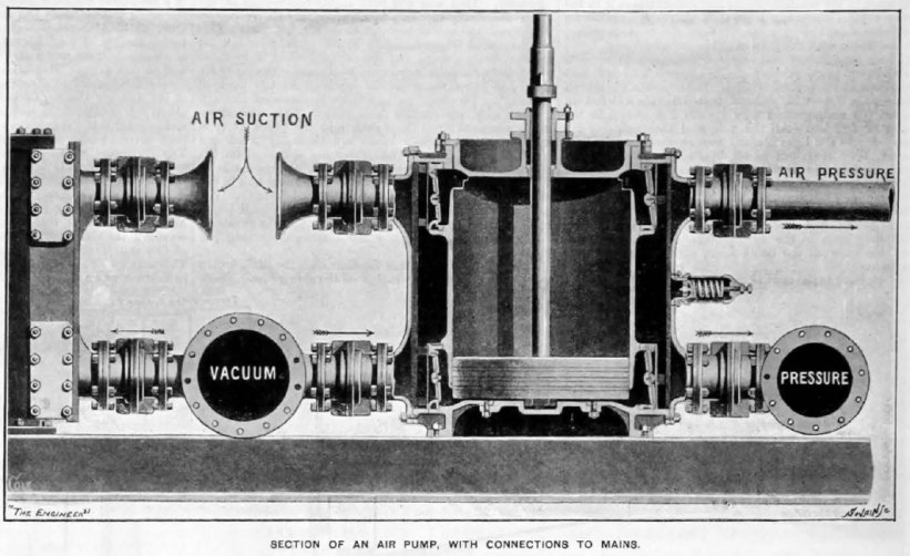 |
| Left: A section of one of the vacuum/pressure pumps at the General Post Office: 1899
The control valves can be seen between the mains and the pump cylinders. Note there is what appears to be a safety-valve on the right side of the pump cylinder.
Image from The Engineer, for 18th December 1899, courtesy of Tom Bates.
|
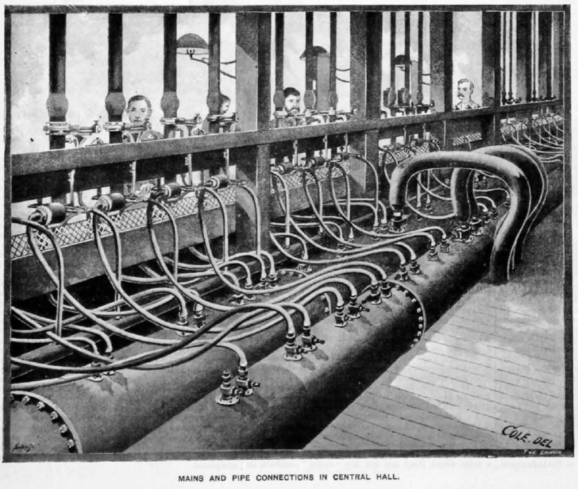 |
| Left: Hose connections between send/receive terminals and the vacuum and pressure mains in the central hall of the General Post Office: 1899
Once again a smaller 'vacuum pipe' is shown.
Image from The Engineer, for 18th December 1899, courtesy of Tom Bates.
|
 |
| Left: The London system: from The Engineer, for 18th December 1899
The local engine referred to was at the GPO Foreign office at top right. Presumably it was a steam engine.
|
 |
| Left: The London system: 1948
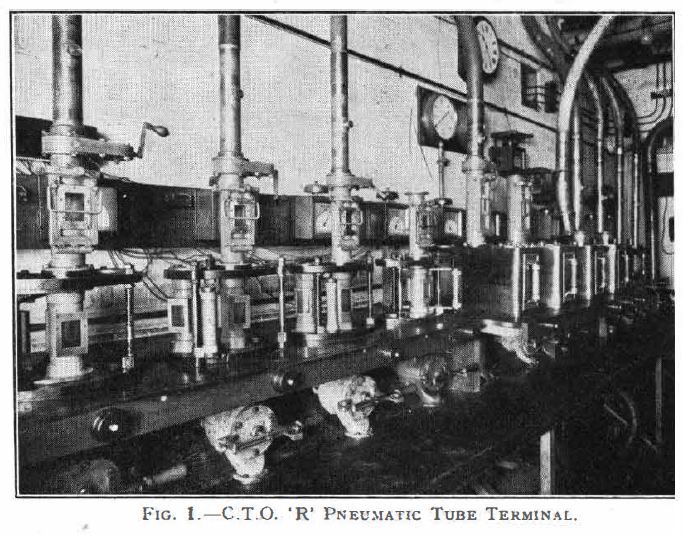
The Post Office pneumatic tube system was badly damaged by enemy action in December 1940. The Central Telegraph Office (CTO) was practically destroyed by fire and all telegraph traffic was transferred to C.T.0. 'R' and other offices in London. In 1943 work on the reinstatement of the main tube system was commenced.
In 1948 there were about seventy tubes in all ranging in length from approximately 300 yards for the tube to Headquarters Building, to approximately 4,500 yards for the two tubes to the Western District office.
Source: The Post Office Electrical Engineer's Journal, for Jan 1948. Vol 40, Part 4
|
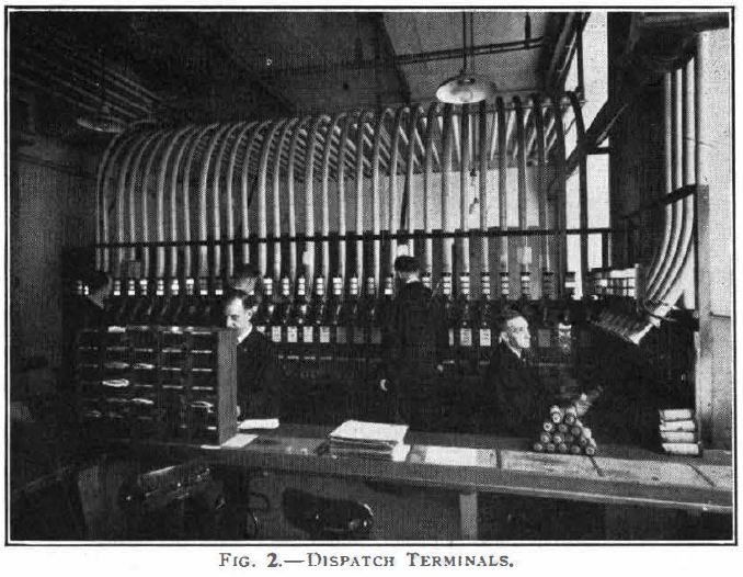 |
| Left: The London system: 1948
The outgoing carriers are dispatched from the tube table shown here.
Source: The Post Office Electrical Engineer's Journal, for Jan 1948. Vol 40, Part 4
|
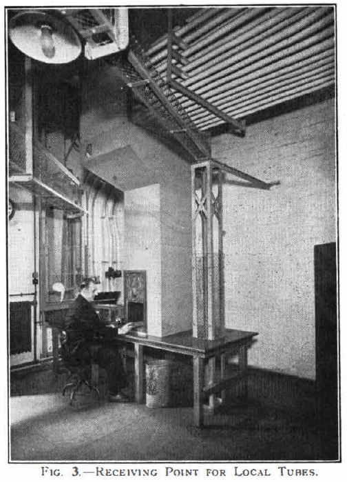 |
| Left: The London system: 1948
There was an innovation in the method of receiving incoming carriers. All the local tubes which carry 'up' traffic to this room from the pneumatic switchgear are terminated in a nest at high level so that carriers are ejected from the open ends of the tubes into a large hopper from which they then fall down a zig-zag chute to table level.
With this arrangement, which is shown in Fig. 3, it is possible to bring all the carriers to one point so that they are within reach of one operator without the use of a conveyor.
The incoming carriers fall down the chute to the right of the operator.
Source: The Post Office Electrical Engineer's Journal, for Jan 1948. Vol 40, Part 4
|
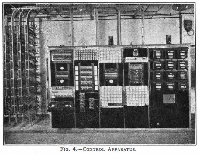 |
| Left: The London system: 1948
This automatic pneumatic switchgear was used to transfer carriers from the 'up' or vacuum street tubes to the local pressure tubes and from the local vacuum lubes to the 'down' or pressure street tubes; it also controlled the supply of pressure, or vacuum, to those street tubes which are worked alternatively in either 'up' and 'down' direction.
The relays and other apparatus used were all of the standard 1948 Post Office telephone type.
|
 |
| Left: Compressor for the London system: 1948
New compressors and vacuum pumps were installed to move the carriers.
Positive-displacement rotary compressor were obtained from Messrs Hick Hargreaves & Co Ltd, of Bolton. The compressors were driven by 80HP Crompton-Parkinson motors over a speed range of 300-600 rpm, and the vacuum pumps by 65-h.p. motors over the range 250-500 rpm.
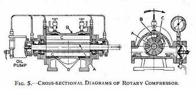
"The solid cast-iron rotor A is mounted eccentrically in the cylinder B and rotates in the direction of the arrow, carrying with it the steel blades C which slide in milled
axial slots. These blades are kept in contact with the cylinder by centrifugal force during rotation of the rotor and sweep through the crescent-shaped space
between the cylinder and rotor. The portion of this space between any two adjacent blades is at a maximum at the trailing edge of the suction port and is gradually reduced as the rotor turns. The air in this space is thus compressed until the leading edge of the delivery port is reached, when it is discharged at the higher pressure. The blades are not actually in contact with the cylinder wall but are held a few thousandths of an inch away by two restraining rings D. These rings are free to rotate in slots in the cylinder wall and are carried round by the blades. The space between the edges of the blades and the cylinder wall is sealed by a film of oil, the friction. between the blades and the cylinder wall being reduced appreciably by this device."
Source: The Post Office Electrical Engineer's Journal, for Jan 1948. Vol 40, Part 4
|
Note the continuous oil supply to both bearings and the two ends of the cylinder. Two manual lubricators were provided for the restraining rings D. There is a pressure gauge and a non-return valve on the output. The non-return valve was to prevent the rotor from reaching an excessive speed in reverse if the power failed.
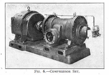 |
| Left: Compressor for the London system: 1948
One of the compressors seen from the inlet side, paired with its electric motor. The oil pump is at the extreme right on the end of the shaft. Air was drawn in from the engine room through a filter of the Visco oil type and a silencer, and the compressed air in each header is passed through a cooler before distribution to the pneumatic tubes.
Source: The Post Office Electrical Engineer's Journal, for Jan 1948. Vol 40, Part 4
|
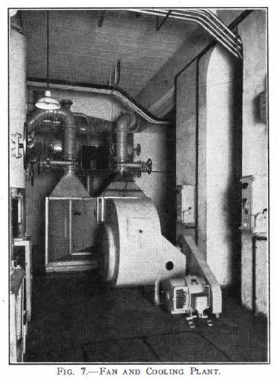 |
| Left: Air cooler for the London system: 1948
When air is compressed it gets hot, so it had to be passed through a cooler before distribution to the pneumatic tubes.
The compressed air was passed through tubes about 2 inch diameter with external gills and cooling air was drawn from the engine room by a centrifugal fan and
blown over the gilled tubes. The fan and driving motor can be seen in the foreground of Fig. 7 with the cooler housing behind. The compressed air passed four times
through the cooling air stream and was cooled from about 180°F to 100°F for air at 12 psi, and twice through the cooling air stream while being cooled from
about 140°F for air at 6 psi. The air coolers were manufactured by Messrs Hunt & Moscrop Ltd, of Apex Works, Middleton Junction, Manchester.
Source: The Post Office Electrical Engineer's Journal, for Jan 1948. Vol 40, Part 4
|
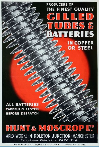 |
| Left: Used in the air cooler for the London system: 1948
Gilled tubes by Messrs Hunt & Moscrop Ltd, of Apex Works, Middleton Junction, Manchester.
|
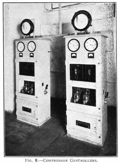 |
| Left: Compressor controllers for the London system: 1948
"The pressure-sensitive device on each controller, which is visible through the lower windows in the controller housing (see Fig. 8), is a small transformer, the primary of which can move relatively to the secondary. This primary winding is mechanically coupled to a bellows arrangement connected to the source of pressure and is loaded by a dead weight applied through a lever so that it stabilises at the required pressure. An increase in pressure causes the coupling between the primary and secondary winding
to increase, and thus, with a constant voltage applied to the primary, the secondary voltage, over a small range, is proportional to the applied air pressure. This secondary voltage is rectified and compared with another unidirectional voltage and the difference, if any, applied to a sensitive galvanometer. When operated the galvanometer closes one or other of its two contacts according to the direction of the difference, and, by means of various relays and the contactors in the starter already referred to, corrects the speed of the associated compressor by causing a movement of the shunt field regulator."
It all sounds a bit complicated.
The control equipment for all the machines was supplied by the Watford Electrical & Manufacturing Co Ltd.
|
 |
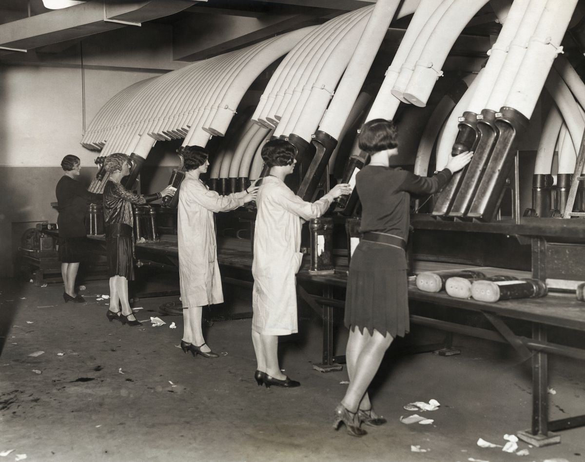
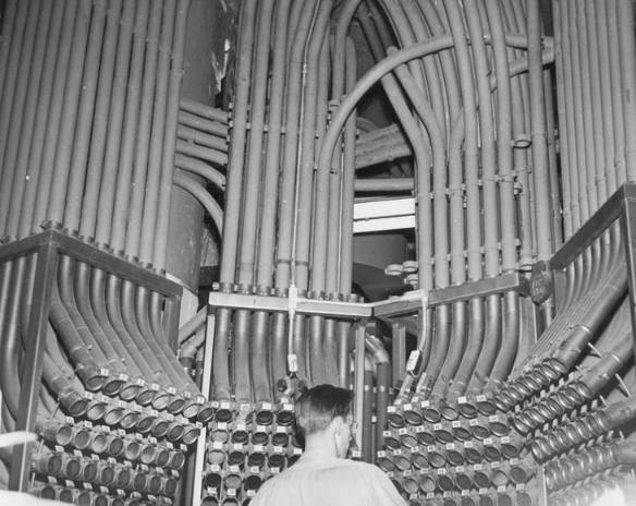
| Left: Pneumatic tube centre in a London typewriter factory: 1950?
This impressive installation was at a London typewriter factory, and that is all that is known. The likeliest candidate is the Remington typewriter assembly facility at 16 Crutched Friars, EC3N, near Fenchurch Street Station; this opened in 1930. The typewriter parts were made in the USA.
Judging by the hairdo and the telephone, this picture dates from the 1950s.
|
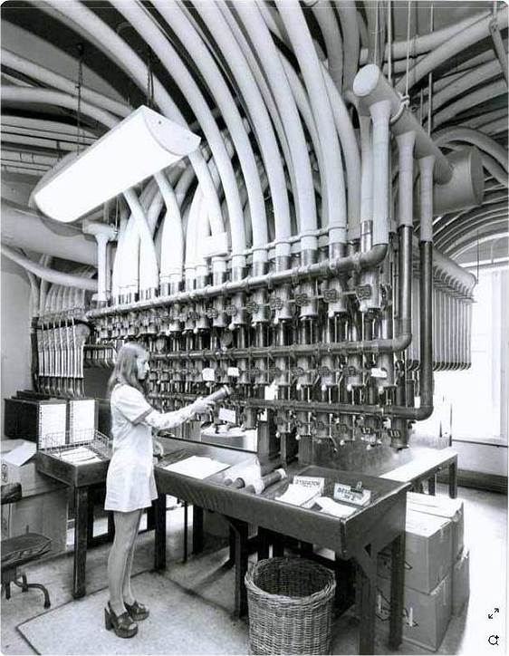 |
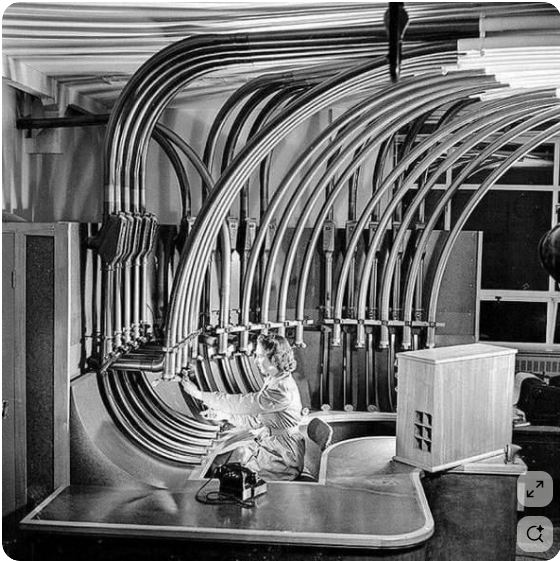
| Left: Pneumatic tube centre : 197?
This installation is at an unknown location, but on close examnation the two documents secured by bulldog clips at the right-hand end of the desk are labelled 'DESPATCH' which suggests Great Britain. The mini-skirt and the platform shoes suggest something like 1968-1973.
There are 18 numbered tubes.
|
PNEUMATIC DESPATCH IN GERMANY: OPENED 1865
Berlin's pneumatic dispatch system began in 1865 and closed in 1976. It was a gigantic pneumatic post system 254 kilometres in total length at its maximum extent. (NB some sources put it as high as 400 km,which is quite a discrepancy) The first installation in 1865 consisted of two tubes, each 2835 feet long and 3.5 inch in diameter, running between the Stock Exchange and Central Telegraph stations in Berlin. It was implemented by Latimer Clark, working with the Siemens telegraph company. At its peak, Berlin had 27 tube lines in a 254km long system, connecting Berlin post offices. Carrier speed was up to 10 metres per second. In 1898 alone more than 2.3 million mail items passed through the tubes.
The Berlin system has a Wikipedia page, with a lot of information.
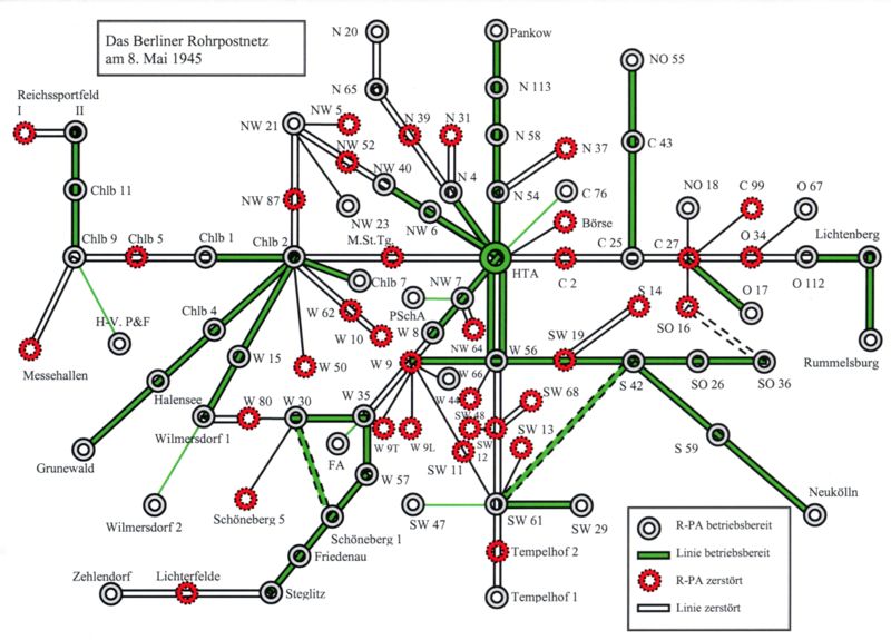 |
| Left: The Berlin network: 8 May 1945
This is the Berlin network at the end of WW2. By then the network had been seriously damaged by bombing.
The green lines and the white post offices are those still operational. (betriebsbereit)
The white lines and the red post offices are those destroyed. (zerstort)
The significance of the exact date is that it was Victory in Europe Day.
HTA at the centre of the map is the main telegraph office.
|
By 1931 an electric routing system was in use so that carriers could be despatched to various destinations after starting off in the same tube.
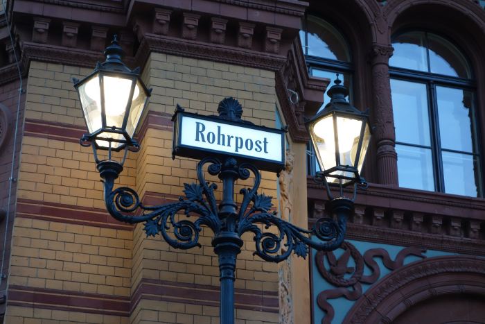 |
| Left: Sign outside a Berlin post office building in 2017
This is the post office building at 35 Oranienburger Strasse, where it crosses Tucholsky Strasse. Rohrpost means 'tube-post'. The building has not been a working post office for some time- possibly not since the tube system closed. Until recently it housed the C O Museum of photography, but is now apparently being rebuilt to become a corporate headquarters.
The Berlin system is mostly dismantled but a few stations are believed to still exist.
Author's photograph; May 2017
|
Perhaps the most remarkable application for pneumatic tubes was inter-table communication in fancy nightclubs. The Resi was a big Berlin nightclub with a band and a dance floor holding a thousand people. An elaborate system of phones and pneumatic tubes at the tables allowed for anonymous flirtation between strangers.
While you could send handwritten note by tube to someone you liked the look of, the Resi offered much more than that. The list of gifts that club-goers could dispatch via pneumatic tube included bottles of perfume, cigar cutters, and, allegedly cocaine. This odd business is well described at atlasobscura.com. The pneumatic flirting system survived WW2, and Americans visiting Berlin afterwards are said to remember it fondly. If we're going to be honest about it, it was more like pneumatic prostitution. So says Philip Kerr in March Violets.
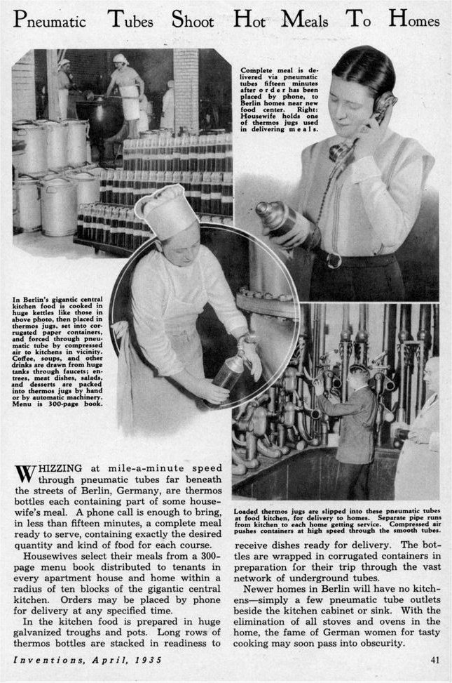 |
| Left: Pneumatic food delivery in Berlin: 1935
This would be one of the most remarkable applications of pneumatic tubes- assuming it is genuine. Rigorous googlage has turned up nothing beyond a few references coming back to this same article, and bearing in mind the month of publication, I have dark suspicions it might be an April Fool hoax. On the other hand, faking photographs with hundreds of thermos flasks lined up wouldn't have been that simple. No Photoshop in 1935.
OK. If we are to believe this then there must have been a pneumatic tube to every apartment and house. That assumes an incredibly dense network of tubes, and so far as I am aware nothing like it was ever attempted. How were the carriers directed to the right destination? It implies a much more sophisticated system of tube-switching than that used in Berlin; however the caption at lower right claims 'Separate pipe runs from kitchen to each home' which sounds completely impractical. No idea is given of the area allegedly served- the implication is that this super-kitchen covers all of Berlin.
Another issue is the size of the thermos flasks; the Berlin pneumatic tube had an internal diameter of 3.5 inches. The thermos flasks illustrated, which presumably would need an outer casing, look too big.
I am also wondering a bit about that 300-page menu book; that's an extraordinary choice of food, implying not less than 6000 dishes (assuming 20 per page) and which alone undermines the credibility of the article. It would be one hell of a kitchen that could cope with that menu over a city the size of Berlin.
I therefore conclude this is indeed an April Fool hoax; given the peculiar and wholly impractical inventions that often show up in magazines of this sort, I submit it is not obvious, and that it is unwise for their editors to stage hoaxes.
From Modern Mechanix for April 1935, p41
|
Amazingly, this idea is not dead; hoax meets hyperloop. An outfit called the Foodtubes Project is planning to cover Britain with high-speed pneumatic tubes to replace the lorries that currently get the food to our supermarkets. I hasten to add the food is uncooked, so it's slightly more practical than highspeed thermos flasks. There is more information at Arstechnica, dated 2010, but nothing much seems to have happened since then.
An interesting question is how big these tubes are going to be; I hope they will be able to cope with delivering Xmas turkeys.
PNEUMATIC TUBES IN MUNICH
A system in Munich opened on 1 August 1922, its completion having been delayed by the First World War. In Munich letters up to a gross weight of 100 gm were allowed. The letters had to be rollable to a diameter of 4 cm. It closed in 1960.
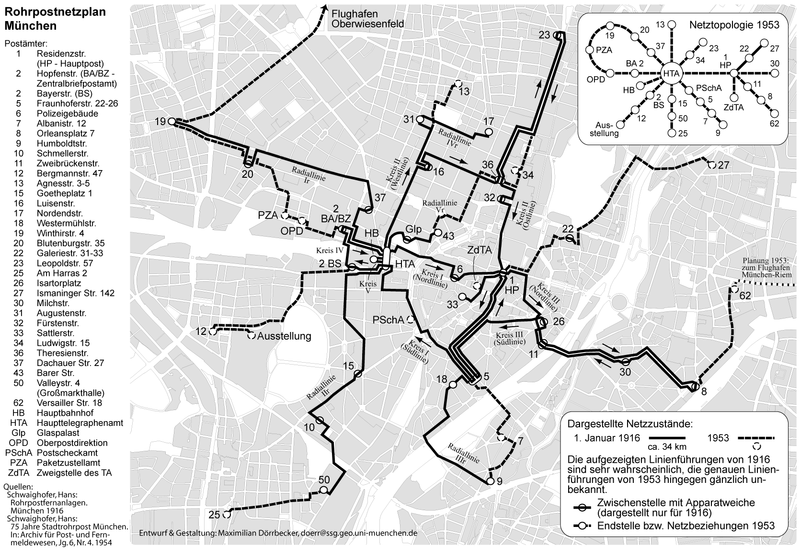 |
| Left: The Munich pneumatic system in 1916 and 1953
HTA is the main telegraph office
HB is the main railway station
|
PNEUMATIC TUBES IN HAMBURG
The first pneumatic post system in Hamburg opened in October 1864. This 65mm-diameter system eventually extended over about 40 kilometers. It is however poorly documented compared with the Großrohrpost (large-tube post) described below.
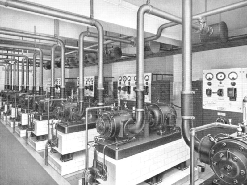 |
| Left: Hamburg small tubes: The engine-room at one of the main post offices
Electric compressors/exhausters are driven by electric motors.
|
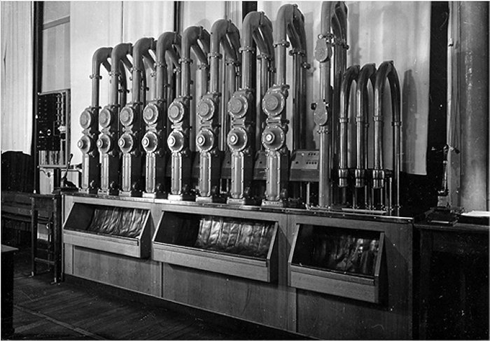 |
| Left: Hamburg small tubes: Transmitting/receiving station: approx 1940
At the Hamburg Stadtrohrpost.
|
 |
| Left: Hamburg small tubes
Location unknown, but presumably at one of the larger post offices.
|
 |
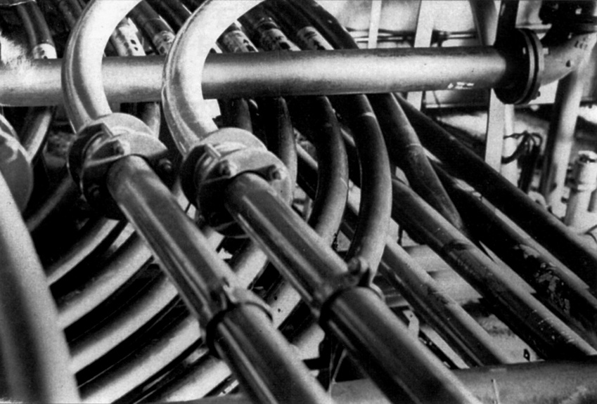
| Left: Hamburg small tubes
Part of the small-tube installation in the basement of the headquarters of the Hamburg Stadtrohrpost.
|
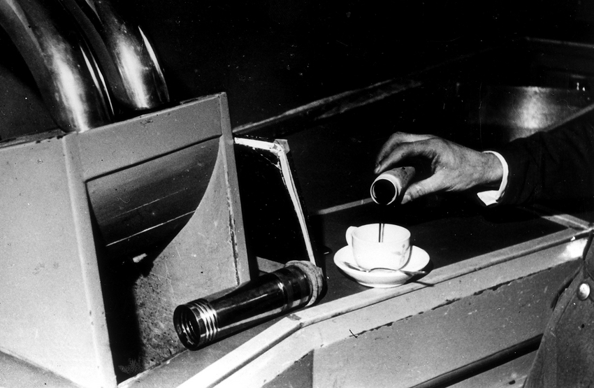 |
| Left: Hamburg small tubes: early morning cocoa delivery
This appears to be real, unlike the April Fool about food delivery all over Berlin. This delivery was almost certainly over a private network: probably at the offices of Die Spiegel, from where the photograph comes.
|
THE HAMBURG GROßROHRPOST
Hamburg was unique in that relatively late in the day it began to build a large-tube pneumatic system with a tube diameter of 45 cm, prompted by congestion in the streets. It was called the Großrohrpost. (big-tube post) Progress was delayed by the 1962 North Sea storm surge, (page in German) and the central ring was not fully operational until May 1967. It closed in 1983, so perhaps building it was not a brilliant idea.
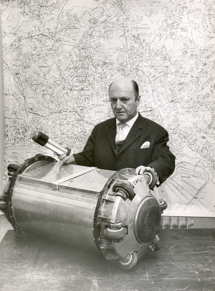 |
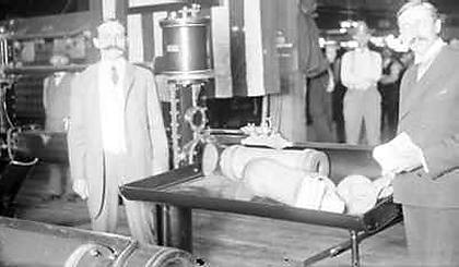
| Left: Hamburg Großrohrpost carrier: 1963
The chief engineer of the Hamburger Grossrohrpost, Dr Heck, shows small-bore and large-bore pneumatic carriers to journalists.
Several carrier designs were tried out; this version is shorter than most and has six wheels at each end.
|
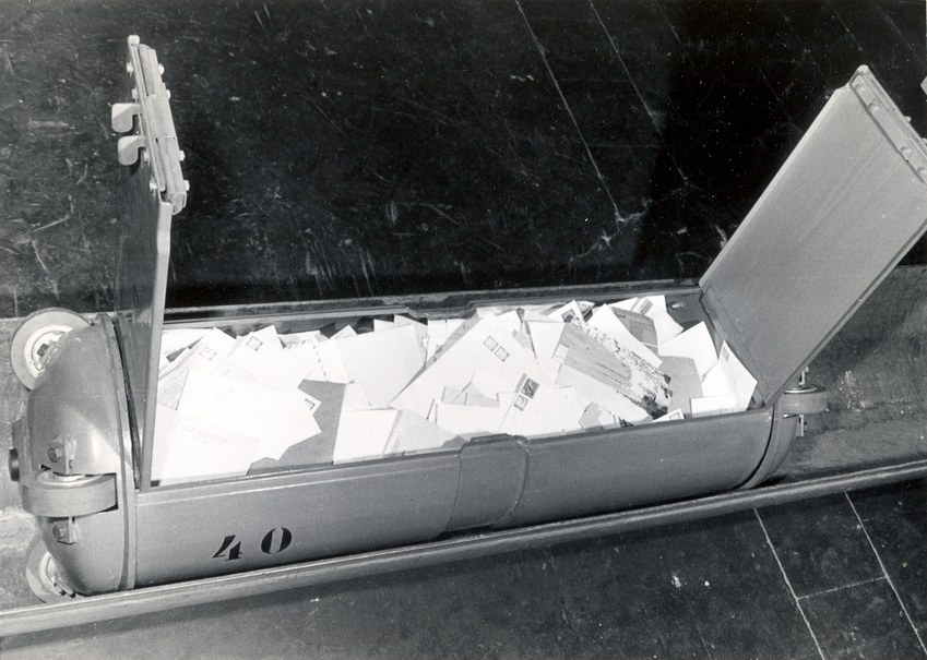 |
| Left: Hamburg Großrohrpost carrier: 1963
It is clear that the big carriers could hold enormous amounts of mail compared with the original small-bore system.
The carrier is 45 cm in diameter; this design was about 1.4 m long with four wheels at each end.
|
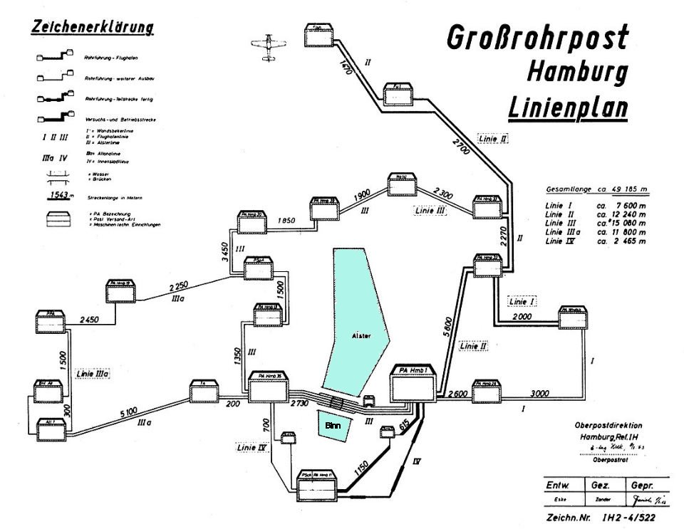 |
| Left: The planned Hamburg Großrohrpost post network: 1963
There were five lines in the Hamburg Großrohrpost sytem.
The two blue areas are large artifical lakes within the city limits of Hamburg; the Außenalster and the Binnenalster.
Considerable difficulty was found in threading the large-diameter pipes through ground already heavily occupied by sewers, water pipes, gas pipes, telephone conduits etc.
More problems were encountered when the system went into operation. Vibration from road traffic damaged the tubes, contributing to its closure.
The Hamburg pneumatic system has a Wikipedia page, (in German) that gives a good deal of information.
|
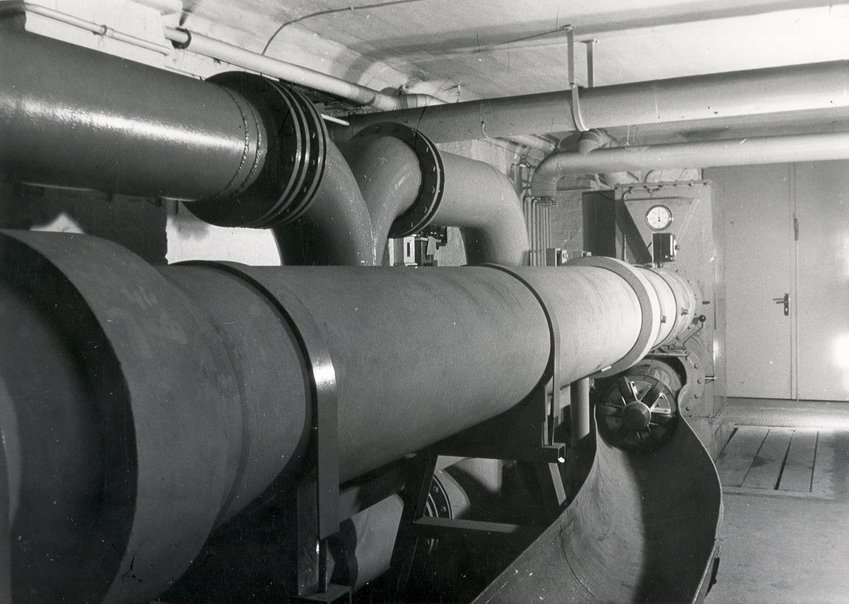 |
| Left: Part of the Hamburg grossrohrpost system
A carrier with six wheels can be seen in the trough at lower right.
Several designs of carrier were tried.
|
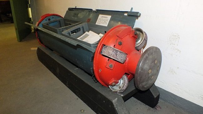 |
| Left: One of the Hamburg grossrohrpost carriers preserved
This carrier design is 450 mm in diameter and 1.6 m long, with anti-friction wheels and a substantial buffer at each end.
It is noticeable that all the grossrohrpost carriers shown here are of different design.
|
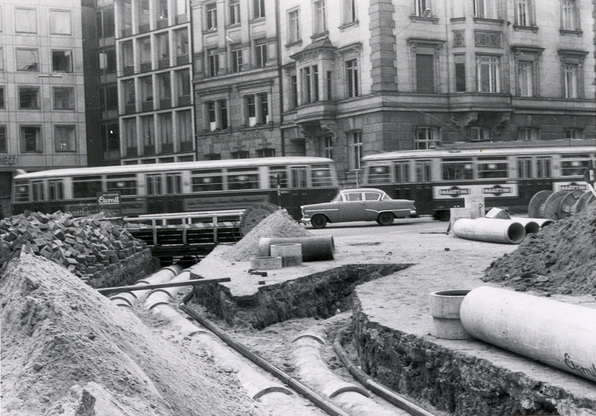 |
| Left: Grossrohrpost tubes being installed in Hamburg
There appear to be small-bore tubes laid beside them.
|
PNEUMATIC SYSTEMS IN FRANCE: OPENED 1866
The first French pneumatic system was opened in Paris in 1866. From 1881 it was extended across Paris, although generally within the pre-1791 octroi zone of Paris; goods could only enter this central walled zone if tax was paid on them. An extension to Neuilly was opened in 1914, but other suburbs were served by bicycle messenger, as plans to extend the system further into the suburbs were suspended due to the 1914-1918 war. The majority of tubes were of 65mm diameter, although 80mm diameter tubes were later used. The tubes were generally laid within sewers. After 1931 a system was introduced to allow capsules to be redirected across the network automatically. The system was used for the transport of postcards and small letters at premium rate. It seems to have survived longer into the electronic age than most partly because it was part of the culture of Paris; a 'petit blue' was a sign that a message was urgent and important. In addition, for a long time the Paris telephone system was relatively unreliable. The pneumatic system was finally shut down in 1983, having become unprofitable.
 | | 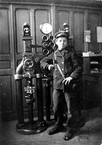 |
| Far left: A pneumatic message centre in Paris
Left: Paris pneumatic telegraph boy
|
In Paris, you went to a pneumatic station, and wrote your message. This was sent pneumatically to the office nearest its destination; its journey was completed by a courier. The process was called sending a "petit blue", from the colour of the forms used. La Bourse is the Paris stock exchange.
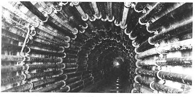 |
| Left: Pneumatic tubes installed in a Paris sewer
Here the maximum possible number of tubes has been fitted into a sewer, limited by the size of the flanges joining lengths of tube together.
|
THE OPERATION OF THE PARIS SYSTEM IN 1874.
The first circuit was centred on the central electric telegraph station at Rue de Grenelle. Trains of canisters departed every quarter of an hour from Rue de Grenelle, covering the 1500m to the next bureau (Rue Boissy-d'Anglas) in 90 seconds. The canister carrying messages for local distribution was removed, another carrying messages handed in at that bureau was added, and the train sent off to the next destination, Grand-Hotel. From there it proceeded to La Bourse, Place Theatre-Francais, and Rue des Saint-Peres. It finally returned to Rue de Grenelle, having taken 12 minutes on its round trip.
Each train was composed of ten canisters, together weighing about four kilograms. Under either vacuum or pressure of about 10 psi the train had an average speed of 1 kilometre in 60 seconds.
 |
| Left: A stepped flange joint between two sections of tube
The tubes were of iron, with an internal diameter of 65mm, the sections being joined with stepped flanges to minimise air leakage. The curves in the line were between 5 and 20 metres in radius.
|
The outward journey was under air pressure applied from the rear; the return was by a vacuum applied in front of the canisters; the same push-pull method as used by the London system. This keeps almost all the machinery at the central office.
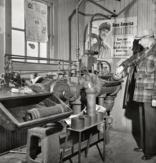
 |
| Left: Air compression by water to power the pneumatic tubes
The trains of canisters arrive & depart via the tube at the bottom. The tank B is initially full of with air, which is compressed by the introduction of water from the Paris mains via the upper pipe b. This method was used in districts where noisy machinery was not permitted. In less sensitive zones conventional steam-powered air pumps were said to be more economical; presumably the Paris water had to be paid for. This method can of course only produce air at the same pressure as the water-main.
Note the U-tube manometer for measuring the air pressure, at the left end of the tank. At the right end there is what appears to be a water-level gauge.
|
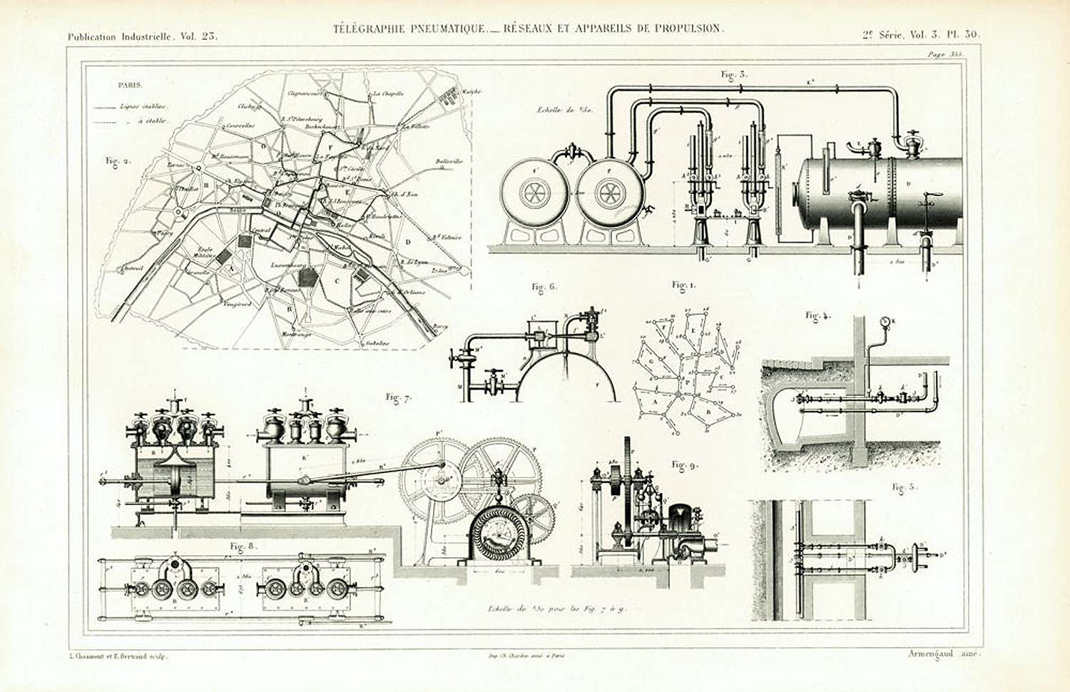
Above: Details of the pneumatic power plants: from Publication Industrielle No 23, date unknown.
At top right (FIg 3) is a water-tank compressing system, looking rather more complex than the picture above, but there are obvious similarities, such as the position of the U-tube manometer. Two send/receive stations are shown, to their right there appear to be two compressed-air reservoirs.
At bottom left (Fig 8) is a steam compressor, with two air cylinders in tandem. Remarkably, this is driven by a steam turbine which is massively geared down to drive the compressor.
At top left (Fig 2) is a map of the network as it currently stood, apparently at some date after the first network map shown below. Fig 1 is a corresponding diagram (somewhat rotated and distorted) showing the direction in which the messages travelled.
In the centre is some sort of water ejector or injector; it is not currently clear how this relates to the rest of the system.
THE PARIS NETWORK
There were three circuits, all running through La Bourse:
Rue de Grenelle
Rue Boissy-d'Anglas
Grand-Hotel
Bourse
Place Theatre-Francais
Rue des Saint-Peres
Rue de Grenelle
| | | | | | |
|
Bourse
Rue J J Rousseau
Rue des Vielles-Haudriettes
Place du Chateau-d'Eau
Porte St-Denis
Bourse
| | | | | |
|
Bourse
Rue Ste-Cecile
Gare du Nord
Boulev. Rocheouart (Montmartre)
Rue Lafayette
Bourse
| | | | | |
|
There were also branch lines to Champs-Elysee, Place du Havre, (for the Gare St Lazare) and Rue des Halles.
 |
| Left: The Paris pneumatic message network when it opened in 1866
This contemporary map of the three circuits was published in La Nature; the exact date is not currently known. Bourse is in the centre of the map.
Unfortunately this image is of poor quality.
|
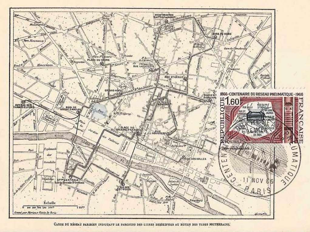 |
| Left: The pneumatic message network in 1866
This commemorative postcard and stamp were issued in 1966 to celebrate the 100th anniversary of the system. It gives a much clearer picture of the original network.
Unfortunately the station at Place du Chateau-d'Eau has disappeared under the stamp. That at Rue des Vielles-Haudriettes is just visible.
Note the image of a message canister in the centre of the postmark.
|
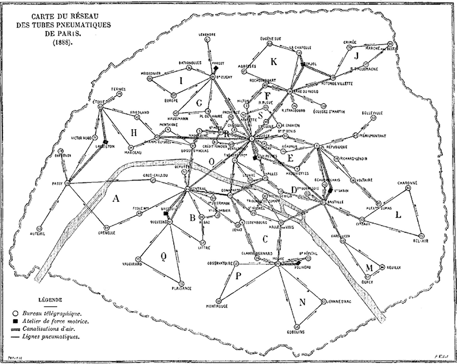 |
| Left: The pneumatic message network in 1888
By 1888 the network has expanded considerably compared with the original layout shown in the maps above.
The seven black blocks are power stations producing compressed air or vacuum, and 'canalisations d'air' are pipelines carrying these to where they are used at the telegraph offices.
Note the arrows by the tube routes. Most routes end in a triangle or quadrilateral so that messages only go in one direction; these are lettered. Some routes are bidirectional.
The jagged line around the network represents the contemporary fortifications of Paris; the Thiers wall built between 1841 and 1844. It was demolished in sections between 1919 and 1929; the Boulevard Peripherique runs round Paris just outside its site.
|
 |
|
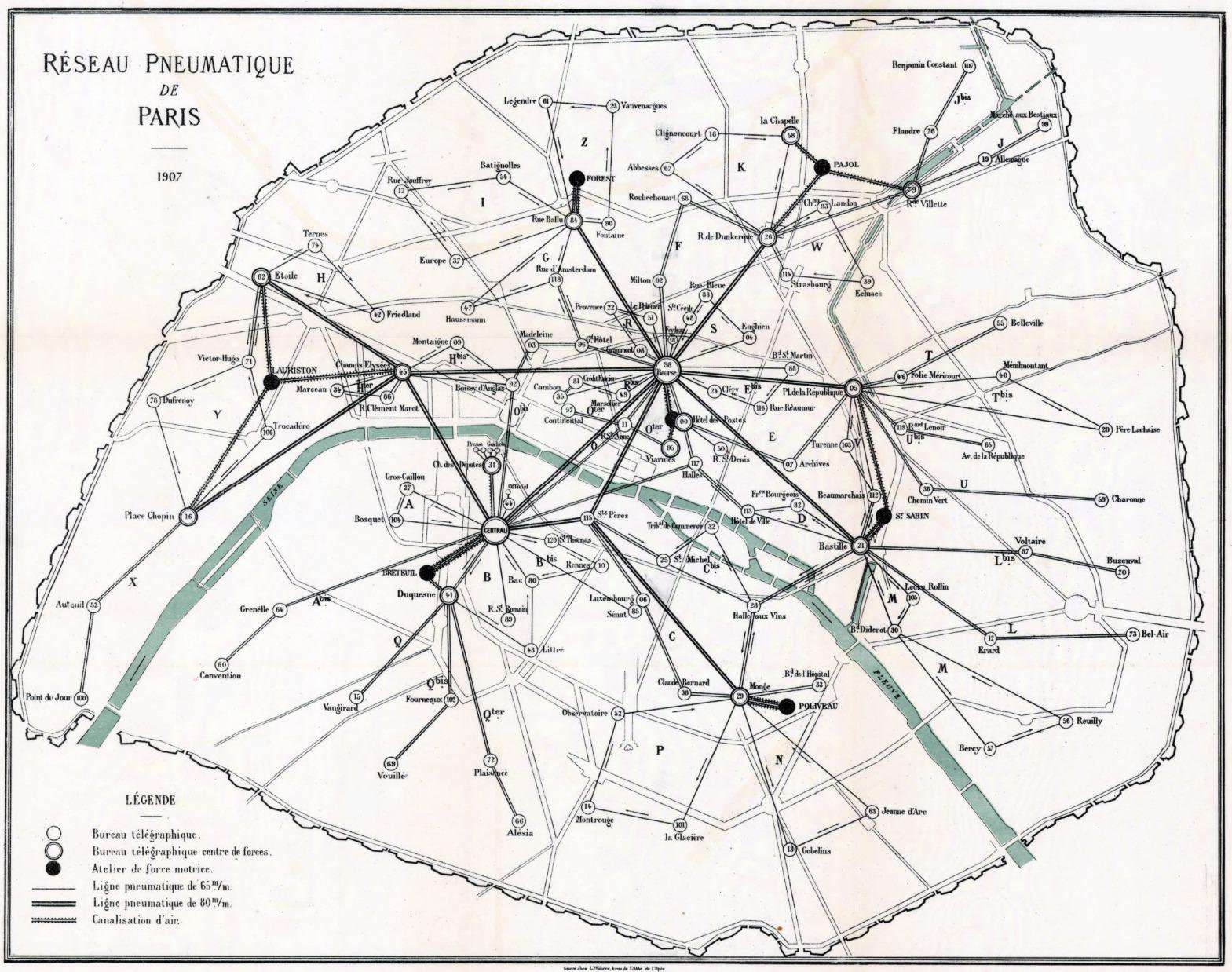
Left: The pneumatic message network in 1907
This is a much clearer map, and from it names that are murky on the 1888 map can be read easily.
By this date installation of the 80 mm tubes was well advanced. Judging by the absence of arrows, all the 80 mm tubes were are bidirectional,
and so the removal or abandonment of the 65 mm triangles and quadrilaterals has begun.
The post office numbers correspond with those of the map above.
The same seven power station locations are in use, with extra pipelines to distribute air (or the absence of it) around the larger network.
Even by 1907, the network did not extend outside the Thiers wall.
|
 |
|
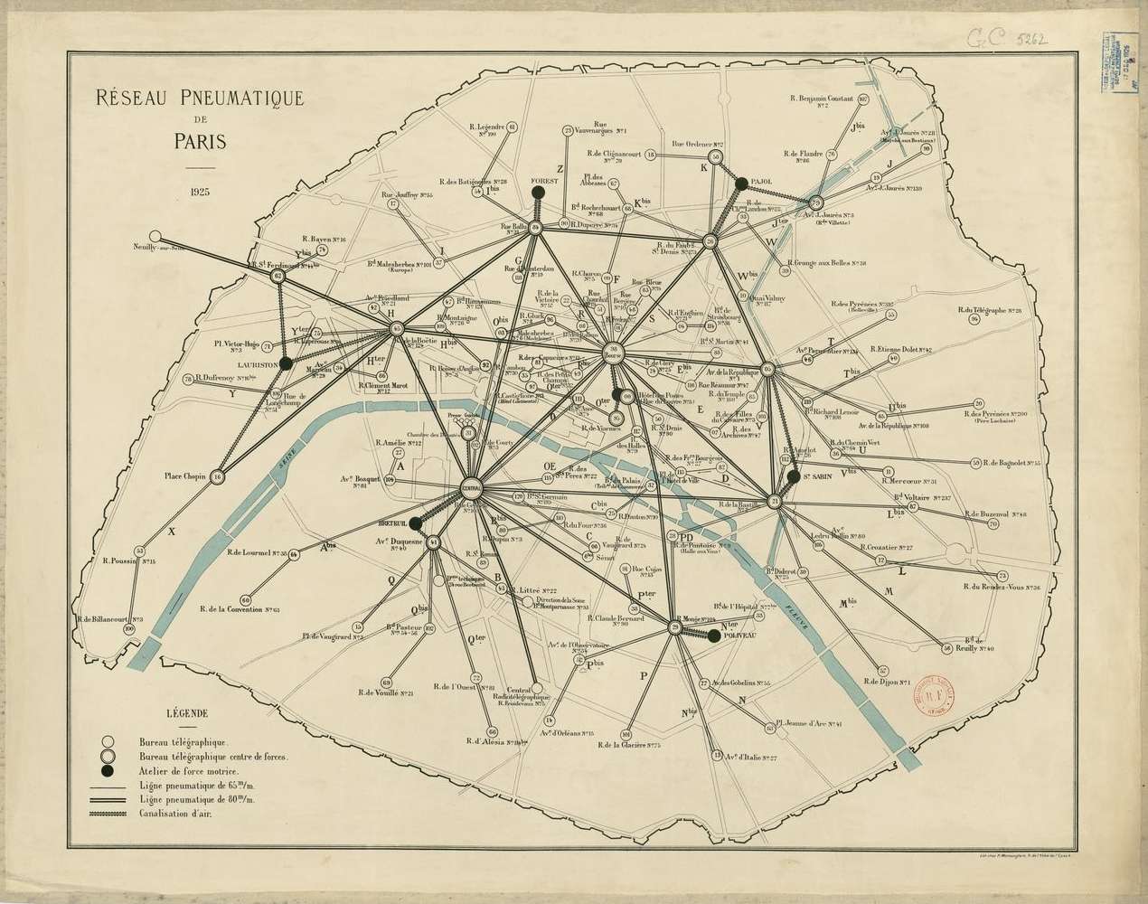
Above: The pneumatic message network in 1925
Much has changed in this 1925 map. By now almost all the tubes were of the 80 mm bidirectional type, for the most of the triangles and quadrilaterals used to turn the messages around have disappeared. Some post offices such as Legendre, have lost their 80 mm pneumatic tube connection. A few 65 mm loops in the centre still exist, such as Routes R, S and D.
The network has at last reached outside the trace of the Thiers wall, extending North-west to Neuilly. The wall has in reality been mostly demolished by this date, though still shown in its entirety on this map.
|
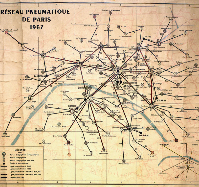 |
| Left: The pneumatic message network in 1967
Again, much has changed in this map of 1967. The Thiers wall has now gone completely. (apart from a small section at Peupliers, not shown) Some post offices such as Legendre 104, have lost their pneumatic tube connection.
The key at bottom left implies that some 65 mm tubes remained in operation at this date, but unfortunately it is not possible to see from this image which they were. Note the key refers to 'ligne pneumatic a selection' which must refer to the automatic routing system introduced in 1931.
|
 |
|
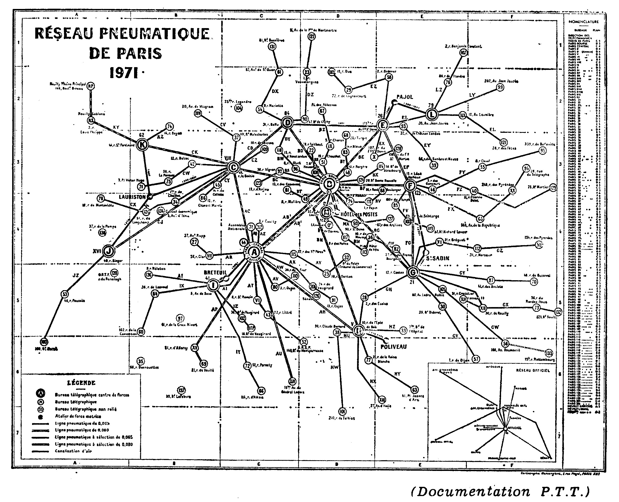
Above: The pneumatic message network in 1971: it does not appear to have changed since 1967.
This is the latest map found so far. Image quality is poor but no better version has been found so far. The pneumatic system closed down in 1983.
|
The Marseilles pneumatic service opened in 1910 and closed on the 29th of February 1964
A pneumatic service was opened in Algiers on April 4, 1910. It continued to function for a few years after Algeria became independent on July 5, 1962.
COMMERCIAL PNEUMATIC SYSTEMS IN FRANCE
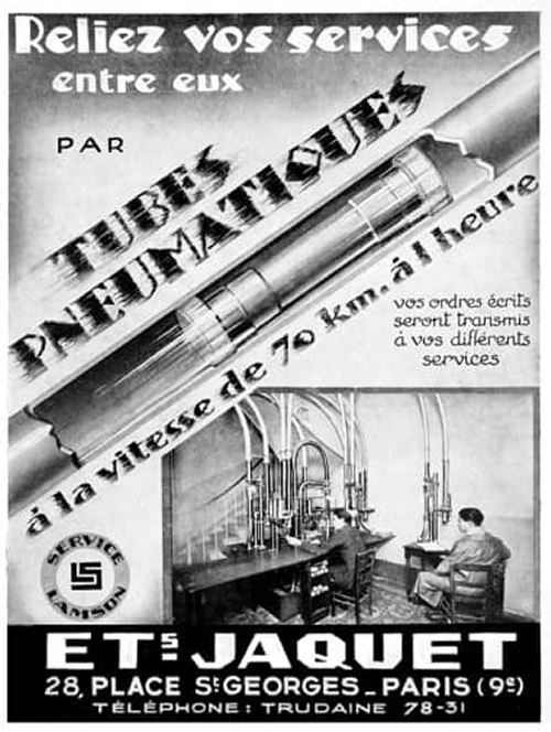 |
| Left: Advert for commercial pneumatic tube system: 1930
This advert was aimed at manufacturers and large shops, who would install their own internal pneumatic networks.
The Lamson Engineering Company were well-known pneumatic tube manufacturers; I assume Etablisements Jaquet were agents and installers.
|
PNEUMATIC DESPATCH IN AUSTRIA: Opened 1875
The system started operating in 1875 in Vienna, linking post offices at distances from 1 and 3 kilometres apart. Initially only 10 post offices were connected, growing to 53 in 1913, with the total length of tubes reaching 825 kilometres. Trains up to 10 pistons long were used. At peak times, up to 20,000 pistons were sent daily. The Vienna pneumatic system was damaged only slightly during World War 1, but the tube system was almost totally destroyed during World War 2, with only 7% remaining usable.
It was rebuilt after WW2 but electrical telecommunications became too strong a competitor and the Vienna pneumatic mail service was discontinued in 1956.
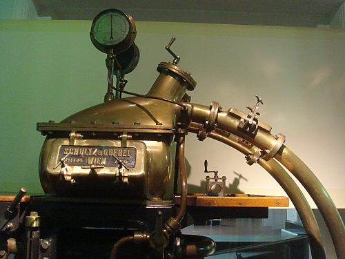 |
| Left: Pneumatic tube machine from the Vienna network
This fine piece of brasswork by Schultz & Goebel is in the Vienna Technology Museum.
At the time the company was run by Theodor Schultz (1845-1911) and his brother-in-law Leon Goebel. (1838-1910) S&G were a well-known company making steam engines, boilers, and pumps; in the second half of the 1880s the factory turned to the manufacture of pneumatic tubes, equipping the pneumatic tube stations in Prague and Carlsbad, as well as Vienna.
The Vienna system now has a Wikipedia page. (In German, but Translate works well)
Author's photo
|
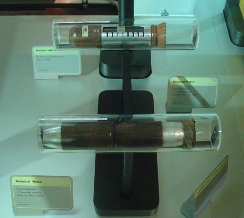 |
| Left: Pneumatic tube pistons used in the Vienna network
These pistons are displayed in perspex tubes, in the Vienna Technology Museum.
Author's photo
|
 |
| Left: Vienna network post office
One of the Schultz & Goebel machines is in the right foreground.
Image in the Vienna Technology Museum.
Author's photo
|
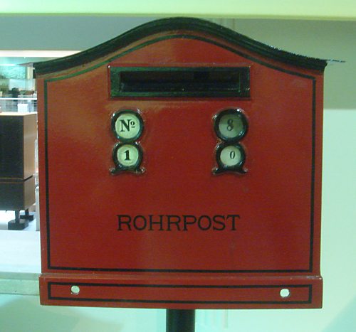 |
| Left: Vienna network postbox: 1900
"Rohr" means tube- so it's the tube-post.
Exhibit in the Vienna Technology Museum.
Author's photo
|
It is believed that a small system existed in Trieste (at the time part of the Austro-Hungarian empire) but this has not yet been confirmed.
PNEUMATIC DESPATCH IN THE USA: Opened 1893
The first American pneumatic tubes were introduced in Philadelphia, in 1893. Boston, Brooklyn, New York, Chicago and St Louis also installed pneumatic systems. By 1915, these six cities had in total more than 56 miles of tubes in use.
The date of opening of the pneumatic postal service in New York so far remains obscure, but was between 1893 and 1898, as by the latter year the NY system connected 21 neighborhood post offices in Manhattan to the main post office branch there. Well into the 20th century, 30% of the first class letters passing through the New York main post office were sent out to the branch offices by the pneumatic tubes.
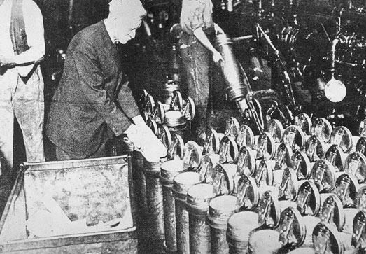 |
| Left: Filling the pneumatic canisters in a New York post office
The angled appliance for sending canisters is in the upper middle of the picture.
|
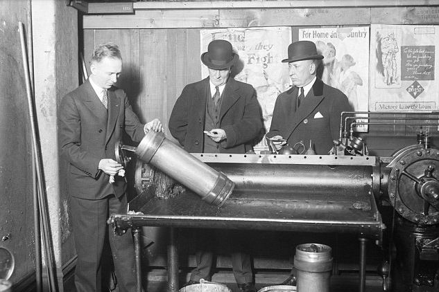 |
| Left: Receiving station in a New York post office: 1917?
This picture is stated to have been taken in 1930, but the Victory Liberty Loan posters on the rear wall suggest it was actually during the First World War.
|
 |
| Left: New York Life insurance company: date unknown
In the USA there were many internal pneumatic systems in large private companies. The ladies are working the tube system of the New York Life insurance company, at 51 Madison Avenue.
The containers are oval in section rather than circular, which was unusual.
|
The pneumatic tube system in Chicago opened in 1904 and grew to a total length of 9 miles.
 |
| Left: The first day of the Chicago postal pneumatic tube service: 24 August 1904
On the right Postmaster Frederick E. Coyne places the first bundle of mail into a pneumatic carrier; note its large diameter compared with European versions. On the left is R W Morrell, a pneumatic tube expert. The Chicago postal pneumatic tube ran between the post office and the Winslow rail station. The tubes were rented from the Chicago Pneumatic Tube Company.
|
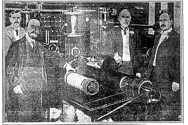 |
| Left: The opening of the Chicago system: 1904
This picture also claims to show the opening of the Chicago system, with different people standing around the receiving station.
I am afraid image quality here leaves much to be desired.
|
This report was issued by the Postmaster-General of Chicago on 31st July, 1905.
"The tube service is now working satisfactorily and is a feature of the service that has resulted in a betterment of the mail facilities. Fifteen minutes' time is gained in the dispatches to outgoing trains at the Union depot, Northwestern Depot, Illinois Central Depot, and La Salle Street depot, after the usual time for closing mails sent by the screen-wagon service, and a corresponding gain on incoming mails from the same depots. About 80 per cent of the mails for the city of Chicago is received and dispatched by the trains using these depots.
"The pneumatic-tube system at Chicago consists of three lines from the new Government building: To temporary post-office and Kinzie Street Station (Chicago and Northwestern depot), 1.83 miles; to La Salle Street depot and Station U (Union depot), 1 mile; to Illinois Central depot, Twenty-second Street Station, Armour Station and Stock Yards Station, 6.05 miles; a total of 8.88 miles, and has been in operation from September 12 and 19, 1904, between the temporary post-office, La Salle Street depot, and Illinois Central depot; from October 3, 1904, between Illinois Central depot, Twenty-second Street Station, and Armour Station; from November 28, 1904, between Armour Station and Stock Yards Station; from December 12, 1904, between La Salle Street depot and Station U; and from March 16, 1905, between the temporary post-office and Kinzie Street Station.
"Since these lines have been in operation, and up to July 27, 1905, the reports show that 717,510,806 pieces of mail have been carried by tube, a daily average of 2,642,701 pieces, the transit time of which was expedited on an average of fifteen minutes, and advanced delivery and dispatch thereby secured. A system of under ground tubes entirely within the control of the postal service, used exclusively in the transportation of mails, free from depredation en route and the interruption of congested street traffic in the part of the city where the main post-office must of necessity be located, is worth more than can be properly shown in any calculation of minutes and money.
"The pneumatic-tube system at Chicago is not fully perfected. Its first few months of operation have indicated defects and that improvements were required. These improvements have been given such attention by the contracting company and its officials that at the present time there are but few interruptions to the service from accidents or other causes. The character of the construction has l)een greatly changed. It is now the practice to lay the bends in bricked chambers, called "manholes," so that ready access to them is provided, and manholes have been put in at intervals of about 350 feet. Now when from any cause a carrier becomes lodged in the tube, it can be gotten at from a manhole not to exceed 175 feet distant, and with jointed rods force can be exerted to dislodge it or draw it back to the open space, whence it can betaken out of the tube. Thus instead of searching blindly for a "stuck" carrier, perhaps in a section of pipe a thousand feet long, with the consequent delay, the new construction allows an early recovery of the stuck carrier and the opening of the line for regular business without unnecessary delay. Bends of a better character are being used and an improved type of terminal receiving machinery has been invented and adopted.
"The occupancy of the new post-office, about October 15, 1905. will remove a serious handicap from the tube service, as there will then be three lines of tube available to send the 2,642,000 pieces of mail daily, while at the temporary post-office the great bulk of the mail must be sent over two lines and unequally distributed between the two, as the northwestern line carries but 20 per cent of the tube mail and the line via the new post-office carries the other 80 per cent."
|
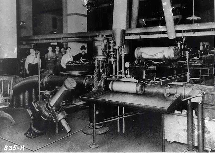 |
| Left: Chicago tube office: 1910
The angled appliance in left foreground is for sending canisters. Behind it is a table for those arriving. The angled sending equipment looks very similar to that used in New York.
|
 |
| Left: At the Marshall-Fields department store in Chicago: 1947
This shows how complex a big private commercial system could become.
|
 |
| Left: Railway communications in Chicago: 1942
A railway yardmaster in Chicago communicates with the central office via pneumatic tubes.
|
PNEUMATIC DESPATCH IN CZECHOSLAVAKIA: Opened 1889
The Prague pneumatic post system (potrubní postí) opened for public use on 4th March 1889. Prague was the fifth city in the world to set up a pneumatic post system; after London, Vienna, Berlin, and Paris. This was considered a major achievement for Prague.
 |
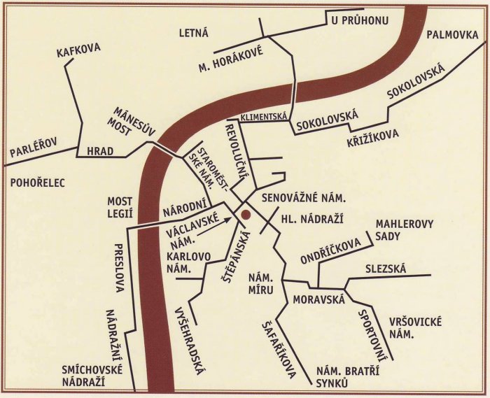
| Left: Prague network: 1890
The first pneumatic tube line was constructed as early as 1887, for internal post office use only. It ran from the main post office in Jindrišská Street, (next to Wenceslas Square, marked 1) to the post bureau at Malé námestí square (next to the Old Town Square, marked 2) in the Old Town quarter of Prague. This first line was later extended west across the Vltava river to the Prague Castle, ('Hrad' on the map, marked 10) making it over 5 km in length.
The tubes are of steel pipes of 65 mm bore and 2.5 to 3 mm wall thickness. The minimum underground bend radius is 250 cm, but 300 cm is the most common radius used.
The Prague Castle was a seat of power for kings of Bohemia, Holy Roman emperors, and presidents of Czechoslovakia. It is now the administrative centre of the Czech republic. It has no direct relationship to Kafka's The Castle, which is set in a village governed from a castle.
|
 |
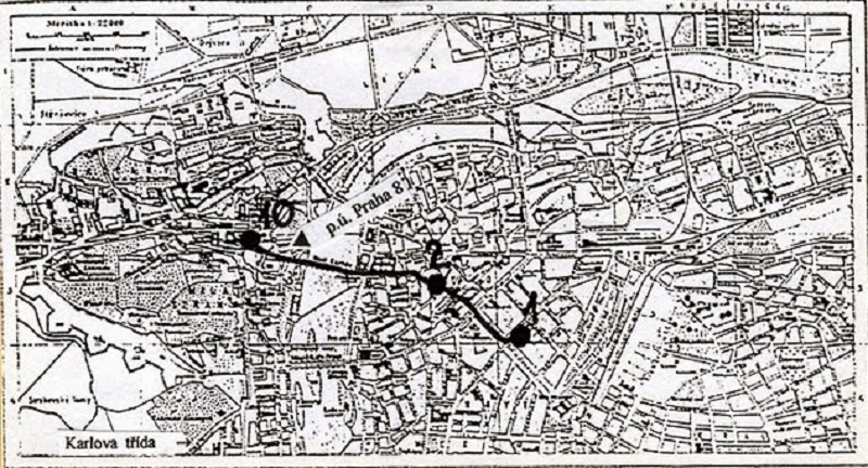
| Left: Prague network later: date unknown
This is not a very satisfactory map, lacking details and date, but it is the best the Museum staff have been able to find so far.
Having just said that Prague Castle has no direct relationship to Kafka's The Castle, it is a little worrying to find a post station and a street called Kafkova on the line serving the castle. Kavkova seems to be another form of Kafka; possibly it was named after the writer but this remains unconfirmed.
Prague, now capital of the Czech Republic, retained its underground pneumatic tube network, approx 60 kilometers in extent, in use until August 2002 when the system was rendered inoperative by the widespread European flooding. Five of the eleven underground engine rooms were flooded and put out of action. The current owner, Telefónica O2 Czech Republic is gradually repairing the system, but due to limited funding the system remained inoperative as of March 2012.
Up to 2002 the Prague system handled about 9,000 transmissions per month, down from more than a million per month in its heyday in the 1960s and '70s.
There is a fine article on the Prague system in Wikipedia.
|
PNEUMATIC DESPATCH IN IRELAND: Opened ??
The only pneumatic postal network in Ireland was in Dublin. No further information available on that at present.
Many large stores in Ireland had pneumatic systems. There is a very good list at www.cashrailway.co.uk which also covers other methods of transmission in shops such as overhead cables.
PNEUMATIC DESPATCH IN ITALY: Opened 1907
 |
| Left: Italian stamp for the pneumatic post service
The Italian involvement in the pneumatic post began late, in 1907, when it was decided to build pilot systems in Rome, Milan, and Naples. Only that in Milan produced useful results, and in 1910 work on a proper Milan sytem began and was finished three years later. After a few years 42,000 metres of tubes were placed and set working, divided into seven lines which issuing from the Palazzo delle Poste. (the central post office building) Progress in Rome and Naples was much slower.
Very little information on the Milan system exists on the internet. Searching in Italian ie posta pneumatica, does not help. All you get is adverts for tyres.
There may have been systems in Florence, and Turin, but these are currently unconfirmed.
There was, and probably still is, a Vatican pneumatic network. It is not yet clear if this had a connection to the main Rome pneumatic delivery system.
I think that is a rather beautiful stamp. I wonder if there are stamp-collectors specialising in pneumatic post stamps; looks as if there are there are.
Pneumatic stamps were issued in Italy from 1913 to 1945.
|
THE MILAN PNEUMATIC NETWORK
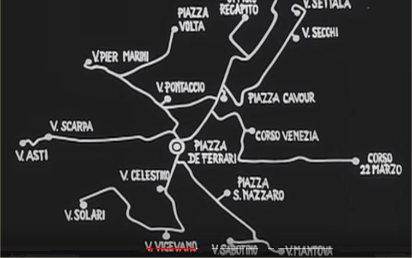 |
| Left: The Milan pneumatic network
This is believed to show the Milan network when it was close to its fullest extent; date unknown.
The first link built was between Piazza de Ferrari and Via Celestino.
All the Italian networks were closed by 1981.
Information on the Italian networks is hard to find, but there is a short film (1 min 42 sec) called La posta pneumatica on YouTube, and this map is taken from there. Careful checking of the post office names and their geographical relationships confirms that it is the Milan network.
|
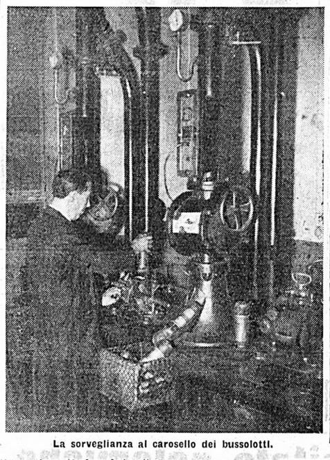 |
| Left: Two machines at a station on the Milan pneumatic network: date unknown
'La sorveglianza al carosello bussolotti' Google translates as 'Carousel surveillance' which does not add much information.
A special counter at each station indicated for the number of carriers received and transmitted.
It is not currently known which station this was.
Apologies for poor picture quality.
|
 |
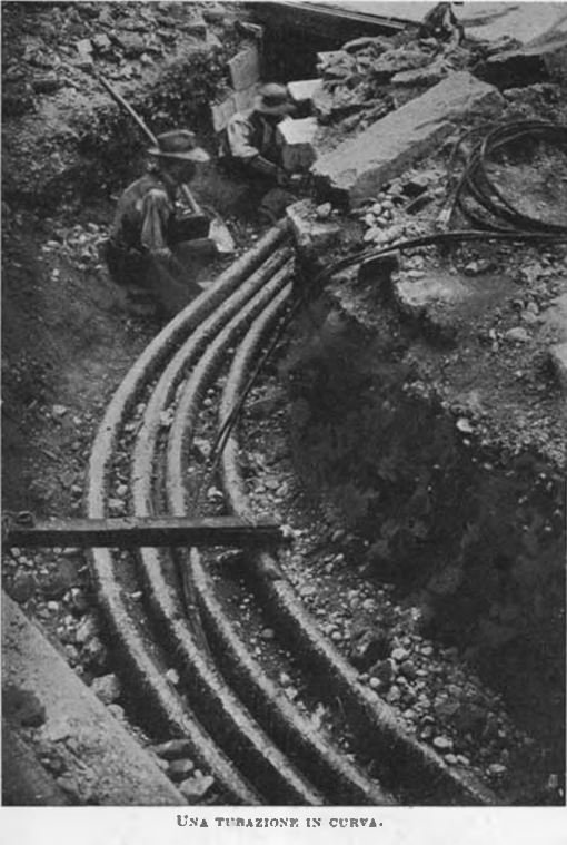 |
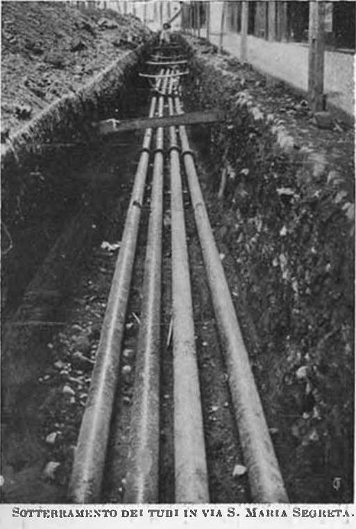
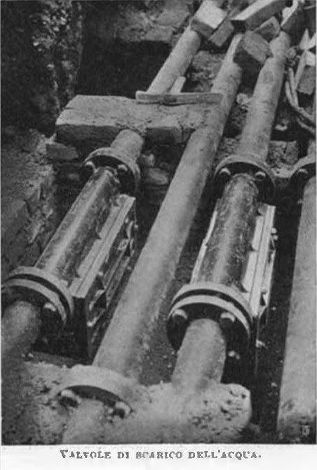
| Left: Pneumatic pipes in Milan: 1910
Left caption= 'Burial of the pipes in Via Santa Maria Sagreta'; this was the road with the Central Post Office at its southern end.
These are the go and return pipes for the two routes, hence four pipes.
Right caption= 'Curved pipes' Since there are four this is probably on the stretch between Central Post Office and Via Giuseppe Pozzone.
The pipes were made in 7-metre lengths, with a wall thickness of 3.5 mm. The diameter was 8 cm, though it is not clear if this was the external or internal diameter. The pipes were buried approximately 1 metre deep.
With the pipes was also buried an electric cable with 5 conductors; two of them were for telephone communication between the four stations. The other three were used for signaling, to indicate to the transmitting office that its carrier has reached its destination.
Images are from the 'Rivista mensile' translating as 'Monthly magazine' of the Touring Club Italiano for 1910.
|
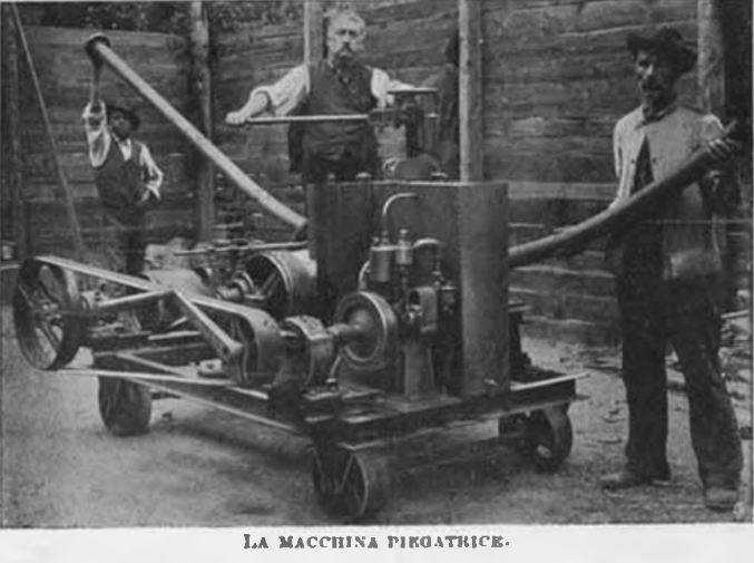 |
| Left: A tube-bending machine used in laying the pipes: 1910
The machine is powered by a water-cooled single-cylinder petrol engine.
|
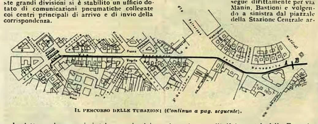 |
| Left: The western end of the Milan sytem: 1910
There were two routes; this map shows the western half of the western route. It ran:
Central Post Office
Via Santa Maria Sagreta
Via Meravigli
Via Dante
Via Rovello
Via Giuseppe Pozzone
From here the line turned sharply west:
Foro Bonaparte
Piazza Virgilio
Via Giovanni Boccaccio
Piazza Giovanni Italia (Terminal office)
This route can be followed on a modern Google map of Milan.
|
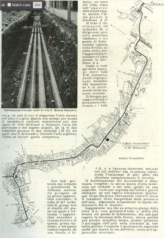 |
| Left: The north-east end of the Milan sytem: 1910
This map shows the centre and north-eastern parts of the system. The Central Post Office is at bottom left; from it the two lines run north and then diverge at B.
Central Post Office
Maria Segreta
Meravigli
Dante
Rovello
Giuseppe Pozzone
From here the line splits from the other and heads north to:
Via Cusani
Via Orso
Via Monte di Pietŕ
Via Croce Rossa (not seen on Google maps today)
Via Manzoni (which had an intermediate station- the black block on the map. Manzoni today marks the west side of the fancy fashion district)
Piazza Cavour
Via Daniele Manin
Via Bastioni
The main railway station
This route can be followed on a modern Google map of Milan.
|
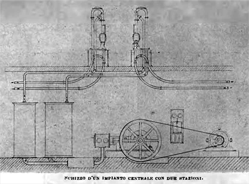 |
| Left: Typical compressor/exhauster installation in Milan: 1910
The caption means: 'Sketch of central plant with two stations' ie two sets of transmit/receive apparatus.
In the basement of the Central Post Office, a 60 HP electric motor drove the flywheel of an air pump which combined compression and exhausting. The air/vacuum passed through dust filters and then was stored in two large tanks from which it was drawn as required to run the pneumatic lines.
|
 |
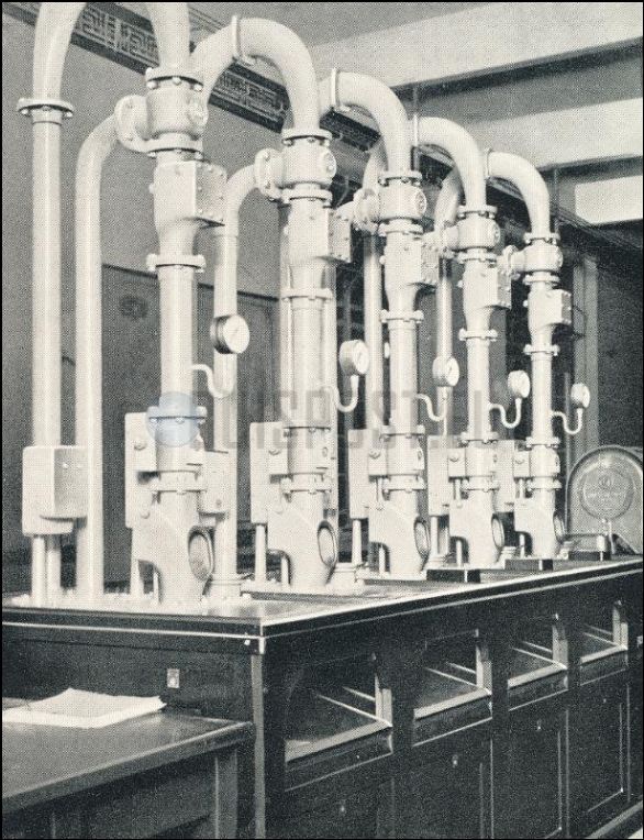
| Left: Valves on the pipes to expel water: 1910
The accumulation of water in pneumatic tubes could be a problem; water vapour in the compressed air would condense in the cold pipes. These automatic valves released the water. Similiar problems were experienced with the Paris compressed-air power distribution system.
|
THE GENOA PNEUMATIC NETWORK
Very little information exists on the Genoa pneumatic system. It has been described as in use from 1953 until the 1980s, (presumably 1981) but that sounds like an implausibly late opening date, exactly 100 years after the start of the London system. Genoa is the sixth-largest city in Italy.
The tube from Via Boccardo (the central Post Office) reached the main railway station through the loading area. The second stretch ran from Via Boccardo along Via XX Settembre, passed in front of the Brignole station and following Via Tommaso Invrea it reached the Post Office in Piazza Tommaseo.
Here is the Wikipedia page for the city of Genoa, but the pneumatic system is not mentioned.
PNEUMATIC DESPATCH IN CANADA: Opened 1928
Pneumatic postal networks were built in Toronto, Montreal and Winnipeg. The Toronto system was the largest, though it was small compared with the great European systems.
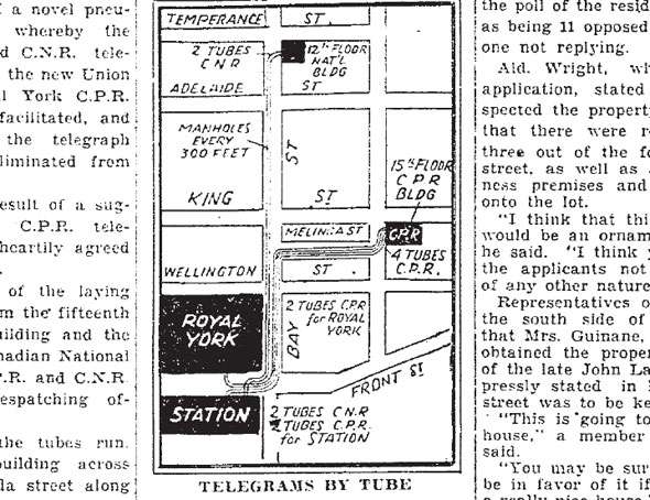 |
| Left: The first Toronto pneumatic tube system
The two big railways of Canada, the Canadian Pacific and Canadian National Railways, rarely co-operated but in 1928 they laid laid down a 4,500 metre pneumatic tube network from their respective transmitting offices - at Yonge Street/Melinda Street, and at Bay Street/Temperance Street - south down Bay Street to Postal Station A at Union Station. Two tubes ran from Union station to the CNR office, and four tubes to the CPR office; the CNR and CPR were not directly connected. A small spur connected to a mail room at the Royal York Hotel.
It took almost a full minute for containers to travel from the 15th floor of the CPR building, down to street level, then south under Bay Street and into to the mail room at Union Station.
The tubes were of copper and of 2.25 in diameter, laid on a concrete foundation and encased in creosoted wood. Manholes every 300 feet down Bay Street provided access to the tubes if a container got stuck. The containers were made of fibre and were 8 inches long.
The Royal York hotel is still there, now called the Fairmont Royal York. It is an enormous building.
|
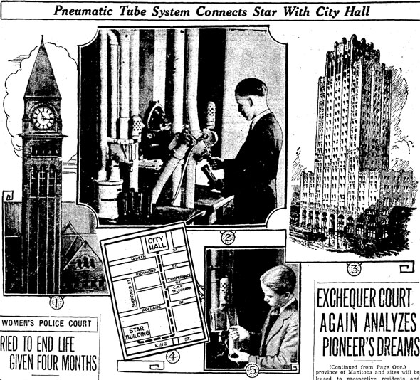 |
| Left: Another Toronto pneumatic tube system
This news item describes a different pneumatic network, running between City Hall (at left) and the Star building, (at right) which was the head office of the Toronto Star newspaper.
This building inspired the Daily Planet building in Superman.
|
At least one major Toronto department store- Simpsons- had a pneumatic tube system for cash and change around 1900.
PNEUMATIC DESPATCH IN SOUTH AMERICA: Opened 1928
Pneumatic postal networks were built in Buenos Aires (Argentina) where they were called 'expreso urbano' (City rapid transit), but the date of construction is currently unknown.
Networks were also built in Rio de Janeiro and Săo Paulo (both in Brazil). Information is currently limited but there is a Wikipedia page (in German) which gives some information on the South American systems.
 |
| Left: Pneumatic tube installation in Buenos Aires
The Buenos Aires system was built by C. Aug. Schmidt & Söhne Company, who began their operations in 1866.
Photograph from the book "100 Jahre C. Aug. Schmidt Söhne, Hamburg". (100 years of...) The book was published in 1941, which does not square with the 1866 date given by Wikipedia.
|
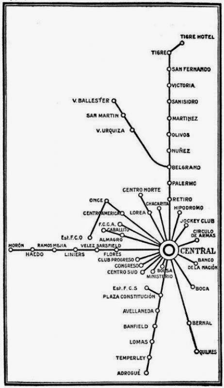 |
| Left: The pneumatic tube network in Buenos Aires
Date currently unknown.
|
CONTEMPORARY USAGE
The pneumatic despatch technology is most definitely still alive within organisations. See ptubes.com (external link)
In fact, a system is being installed in my local hospital.


