Gallery opened: 21 Oct 2015
Updated: 13 Oct 2025
The Sims-Dudley dynamite gun updated once more here.


Pneumatic Guns |
Gallery opened: 21 Oct 2015
Updated: 13 Oct 2025 |
|
Pneumatic guns as such are not rare or unusual. They are very common in the forms of air rifles and air pistols. However, air-powered guns of larger calibre are indeed rare. The early versions such as the Zalinski dynamite gun were motivated by the instability of the shell payload to shock; driving it out of the barrel by an explosion gave a very good chance of it exploding in the gun barrel. This is known in the trade as a 'bore premature' and there is nothing that artillery men fear more. The use of compressed air to expel the shell meant that it could be accelerated relatively gently as it passed up the barrel. The development of more stable shell fillings such as picric acid and Amatol removed this problem and pneumatic guns were at a big disadvantage because of their lack of range, and were abandoned apart from a few niche applications.
Lack of range is inherent in air-powered guns. The highest firing pressure in a pneumatic gun that I am currently aware of is the 2500 psi used by the largest Zalinski dynamite guns. In contrast, a common .22 cartridge can generate 16,000 psi and the US .30-06 rifle cartridge regularily reached 50,000 psi in the breech, with higher pressures reached in proof tests. Modern lubricated reciprocating compressors achieve 4500 psi, and non-lubricated reciprocating compressors 1500 psi. (The distinction is vitally important in the chemical processes where oil contamination must be avoided, but is unlikely to be a problem with pneumatic guns) These compressors are very large, heavy, and expensive and require enormous amounts of power, as compressing air is a very inefficient business. A great deal of heat is liberated as the air is compressed, and unless there is some way to use it locally all its energy is lost. Since the pneumatic gun compressors were sited away from the guns the heat would inevitably be lost and the whole process was highly inefficient.
They did not however disappear for good; it was noted by Theodore Roosevelt, during the Spanish�American War, that the Sims-Dudley dynamite gun was relatively quiet and did not emit smoke, and so did not draw counter-battery fire. Several of the combatants in WW I made use of pneumatic mortars to fire shells a short distance with a high trajectory, the Austrians being particularly keen on the idea, but there were no pneumatic guns as such.
This page deals only with guns and mortars powered by air. There have also been guns designed that were powered by gas, (usually CO2) by steam, and in one baroque example powered, at least in part, by exploding a mixture of ether vapour and air, using the Diesel effect. These others deserve pages to themselves.
![]()
THE TECH OF PNEUMATIC GUNS
1) There must be a sufficient local reservoir of air so the pressure behind the projectile builds up quickly, and a fast-acting valve to apply it. If it does not the projectile will just slide slowly out of the end of the barrel, flopping nose-first onto the ground. If it is fitted with an impact fuse, things will not end well. Some pneumatic ordnance used some kind of detent. (eg a screw that sheared when launch pressure was reached)
2) The compressed air must be cut off in a timely fashion, preferably just as the projectile leaves the barrel. The high-pressure air is a precious commodity, created by the expenditure of a lot of fuel, and it must not be wasted.
![]()
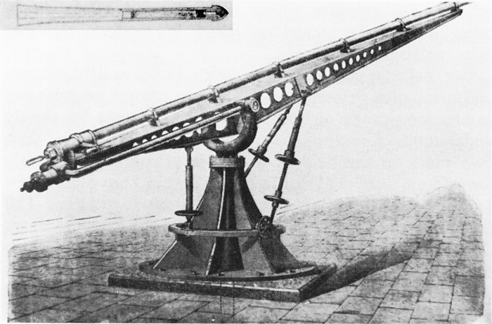
THE MEFFORD DYNAMITE GUN
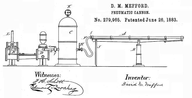 | Left: The Mefford dynamite gun: 1883
|
The picture shows a supporting girder undeneath the barrel, which being much lighter in construction than a conventional barrel, would otherwise droop. This was also a feature of the Zalinski dynamite gun.
Mefford was granted an earlier US Patent No. 252,488 in 1882, but this describes a recoil system for a conventional gun.
The picture shows a simple one-stage compressor driven by steam. This would be a very inefficient way to compress air to 500 psi- a two-stage compressor with intercooling would be much better.
The Mefford dynamite gun has no Wikipedia page.
![]()
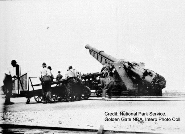
THE GRAYDON DYNAMITE GUN: 1889
The Museum Staff have recently uncovered reports of another pneumatic dynamite gun, put forward by a Lieutenant Graydon. The only information that has emerged so far is two newspaper reports. This is rather curious because if the reports are to be believed the Graydon gun was a large-scale operation, involving a gun that weighed 11 tons just for the barrel. There is plenty of information to be found about the Zalinski gun, why not the Graydon?
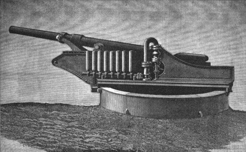 | Left: The Graydon gun: 1891
|
The photograph above shows a large U-shaped pipe that apparently introduces the compressed air through one of the trunnions; the bulging part may be the control valve. To the left of this are what appear to be eight vertical air reservoirs. The total reservoir capacity looks small compared with that used by Zalinski and it is not clear how the compressor was connected.
This news item below appeared in The Queenslander on Sat 14 Dec 1889, p1131:
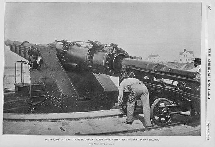
THE ZALINSKI AND GRAYDON GUNS: WAR OFFICE EXPERIMENTS."In order to give the War Office an opportunity of judging of the comparative merits of the Graydon and Zalinski systems, a trial (the Birmingham Post Bays) will take place some time next year at Portsmouth; not, as in America, with dummy shells, but with charged ones. With a view to this trial, the syndicate formed for working the Graydon patents (numbering now thirty-eight) have contracted with Taunton, Delmard, Lane, and Co, Limited, of Birmingham, for the manufacture of a 15-inch torpedo-projector. This will be 30ft. long, as compared with a length of 55ft, which is necessary for throwing the same sized projectile containing 600 lb. of dynamite from a Zalinski gun. And whereas the range of the Zalinski is a little over a mile, the Graydon projector will land its torpedo in a fort or on a ship three miles distant. These two advantages� greater wieldiness in tbe weapon and greater range� are in part due to the fact that Lieutenant Graydon employs a pressure of 5000 lb to the square inch, while Zalinski only uses a pressure of 2000 lb. A bill has been introduced in the United States Congress for the purchase of a large number of pneumatic guns to fulfil certain conditions, which at present are only fulfilled by Lieutenant Graydon's projector. Though the guns would be made in America, it is likely, in the probable event of the Graydon gun being selected, that the orders for tbe compressors would for some time be placed with the Birmingham firm." |
Note that Zalinski is mentioned, and so must have been active in 1889.
The above report was published, with some variations, by newspapers all over the world. This version below from The Practical Engineer for 1st November 1889 gives some more details at the end. The text duplicated above is grayed out:
THE MANUFACTURE OF DYNAMITE GUNS IN BIRMINGHAM."In order to give the War Office an opportunity of judging of the comparative merits of the Graydon and Zalinski systems of torpedo warfare, a trial will take place sometime next year at Portsmouth, not � as in America� with dummy shells, but with charged ones. With a view to this trial, the syndicate formed for working the Graydon patents � numbering now 38 � have contracted with Taunton, Delmard, Lane, and Company Limited, of Birmingham, for the manufacture of a 15in. torpedo projector. This will be 30ft long, as compared with a length of 55ft, which is necessary for throwing the same sized projectile containing 6001b. of dynamite from a Zalinski gun. And whereas the range of the Zalinski is a little over a mile, the Graydon projector will land its torpedo in a fort or on a ship three miles distant. Messrs. Taunton, Delmard, Lane, and Co. have obtained the contract on account of their unique success in making tubes to resist these heavy pressures, compressed air work being one of their specialties. At present only the 15in. gun has actually been ordered, but negotiations are proceeding, as the result of which it is hoped the order will come to Birmingham for a 6in. siege gun, throwing a torpedo charged with 70 lb of dynamite. The whole of the equipment of the guns, including carriages, compressors, and boilers, will be made by the same contractors. The larger gun, with its complete outfit, costs about �10,000, and though the full complement of compressors will not be furnished with the experimental weapon, the present order is obviously an important one as affecting local trade. The first gun will take till Christmas to complete." |
And then this appeared a year later in the Daily Alta California, Volume 83, Number 182, 29 December 1890:
LARGEST DYNAMITE GUN.It Has Just Been Finished and is to use Compressed Air. (Pall Mall Budget) "Messrs. Taunton, Delmard, Lane & Co. of Birmingham are just finishing tbe largest dynamite gun which has yet been made. The explosive contents are made up for greater safety in tiny waxen pellets, and lodged in a shell, the true flight of which is secured by a tapering telescopic tail; and the gun is to be discharged by the expansion of condensed air at a pressure of 5000 pounds per square inch, tbe impulse of which is a safer propelling energy than the ignition of any kind of powder, because it does not operate so suddenly as to cause a danger of the premature explosion of the missile. The telescopic tail enables Lieutenant Graydon to shorten his shell by one half, and to reduce proportionately the length of the impulse tube or gun proper, while the uso of a pneumatic charge makes it possible, without danger, to construct the shell more flimsily than would otherwise be the case." "The contract -with Messrs. Taunton & Co. is for a 15-inch torpedo projector which will throw a charge of 500 pounds of dynamite a distance of three miles; it is expected that this contract will be followed by orders for still larger weapons. As soon as the gun now in hand is delivered there will be a trial of its powers at Portsmouth against the Zalinaki gun, not with dummy shells, as in the case of the American experiments, but with actual charges of dynamite. The noise of the discharge being small, the projectile might be dropped into a fort or onto a ship without giving the besieged any intimation of the quarter from which the attack came. The concussion when the dynamite exploded would in all probability be violent enough to put a large garrison hors de combat, even if they were not wounded by debris; and, truly aimed, a single shell would destroy an ironclad. The barrel, or pneumatic tube, of the gun is of Whitworth forged steel, and weighs about eleven tons."
|
"It (the barrel) is supported at the breech end on fixed trunnions 15in in diameter, which are hollowed for the passage of the compressed air. Towards the muzzle it is carried on movable trunnions engaged with two forged steel arms or levers. These clevers have sliding fulcrums, and are actuated by a hydraulic plunger for the purpose of elevating or depressing the gun. The breech is closed by means of a steel screw-block with interrupted threads, as in heavy service ordnance.""A peculiar feature of this particular Graydon gun is that it can be loaded at any degree of elevation in its working range. Pivoted to the breech trunnions there is a loading slide or tray fore the reception of the projectile or torpedo, the weight of which is about one ton. This slide, at all times when the barrel is elevated above the horizontal line, rises by hydraulic pressure to receive the projectile from a tram trolley. By opening a valve the slide is then made to descend with its load, and becomes lineable with the barrel of the gun. On each side of the barrel is fixed a small double-acting hydraulic cylinder, the plungers of which not only control the movements of the loading slide, but also, by their continued action, draw the projectle up into the barrel, where it is held. The breech-closing block, suspended above the trunnions by counterweights, then descends, and is also drawn into the breech by the crosshead of the hydraulic plungers, and locked. The gun is now ready for discharge." "The compressed air reservoirs, a complement of which numbers thirty-two, are 4ft long and 10in in diameter, are metal of metal 3/4in thick, and are the invention of Mr Lane. They are tested to a pressure of 4 tons to the square inch. They are carried with the gun in four sections of eight each, two on each side of the gun carriage. Filled with air compressed to 5000 lb per square inch, or about 1/340 of its original volume, the capacity of each at the working pressure is 17,000 cubic feet of air, weighing 11cwt in its compressed condition. Any number of the four sections may be discharged, according to the range desired or the weight of the projectile. The discharging valves are a peculiar arrangement of the piston type, and are packed on the hydraulic system. All valves and pipes, were not forged, are of Whitworth cast steel.The carriage on which the gun is mounted is constructed of heavy steel plates, with massive trunnion bearings of cast iron, secured to it buy means of numerous turned bolts. The carriage i ssupported on the roller path with conical rollers geared together and actuated by a Hennan & Froude spherical engine, the motive power of which is also compressed air. The roller path, which will ultimately be bedded in concrete, is made of sections of cast iron. It is 21ft in diameter, and is planed on its surface." "The air from the compressors is passed to the reservoirs on the gun-carriage through a central pivot or swivel-tube. The gun can be loaded, elevated, trained, and discharged by one person. With the gun there is of course a special air compressor. this is a modification of the high-pressure machines designed by Mr H Lane (now largely in use in this country, and adopted by several foreign governments) for oxygen, hydrogen, and carbonic acid. The air is compressed in four operations, the piston decreasing in diameter at each stage. The first, which draws the air from the atmosphere, is 12in in diameter, and the last, which delivers it to the reservoirs, is 2-1/4 in. After each operation the air is cooled by a tubular coil, surrounded with water." "The designing and the construction of the pneumatic gun has been carried out by M Lane, engineer to the company, under the supervision of the inventor, Lieutenant J W Graydon, of the United States Navy who has been residing in Birmingham with that object. It is in some measure due to him that the apparatus for throwing highly-explosive shells considerable distance with accuracy is at present engaging the serious attention of all the Powers. a pneumatic gun is now being erected at Shoeburyness for trial by the British Government, and the United States Government has not only spent already a great deal of money on this class of weapon, but has set aside funds for the purchase of 25 of them. Five European governments have sent representatives to Birmingham to see and report upon the Graydon project during its construction; and the Chinese and Japanese and South African governments profess themselves greatly interested in its success." |
The reference to a Heenan & Froude spherical engine caught my eye. This is none other than the remarkable spherical engine of Beauchamp Tower. Heenan & Froude were the manufacturers.
This all seems very mysterious. The Zalinski gun is quite well documented, and many photographs and drawing of its various versions are available. But there is no trace of any image for the Graydon gun, although it must have been a substantial piece of machinery with its 15-inch 11 ton barrel. The Museum Staff are suspicious by nature, and wondered if this might be an imaginary gun thought up for stock-market fraud. On the other hand Messrs. Taunton, Delmard, Lane & Co. of Birmingham were a genuine and well-respected firm with great expertise in high pressures, and it seems very unlikely they would have involved themselves in criminal stock-promotion. Four-stage compression with intercooling is described, and seems an eminently practical way of reaching the required pressures.
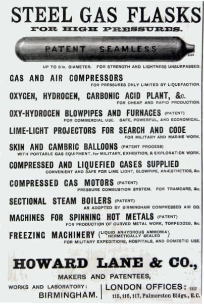 | 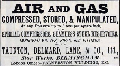
Advertisements for the Howard Lane and the Taunton, Delmard, Lane companies. They are clearly well up in the high-pressure business.
|
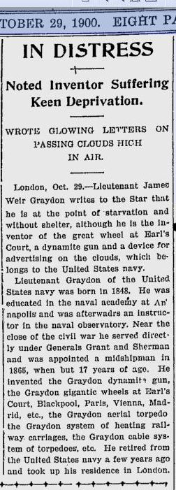 | Left: This appeared in a San Jose newspaper on 29 October 1900
|
There were at least two more little-known dynamite guns; one by Maxim. The other was by Dr Joel Gilbert Justin, which attempted to fire dynamite shells with conventional gunpowder; the dynamite was in the form of little balls embedded in wax, but this does not seem to have helped much. At a demonstration on 27 May 1890 a modified cannon exploded, putting the watching crowd in great peril, though no-one seems to have been seriously hurt.
Research continues...
![]()
THE ZALINSKI DYNAMITE GUN: 1894
 | Left: Early Zalinski dynamite gun: 1894
|
The Zalinski dynamite gun has a Wikipedia page.
|
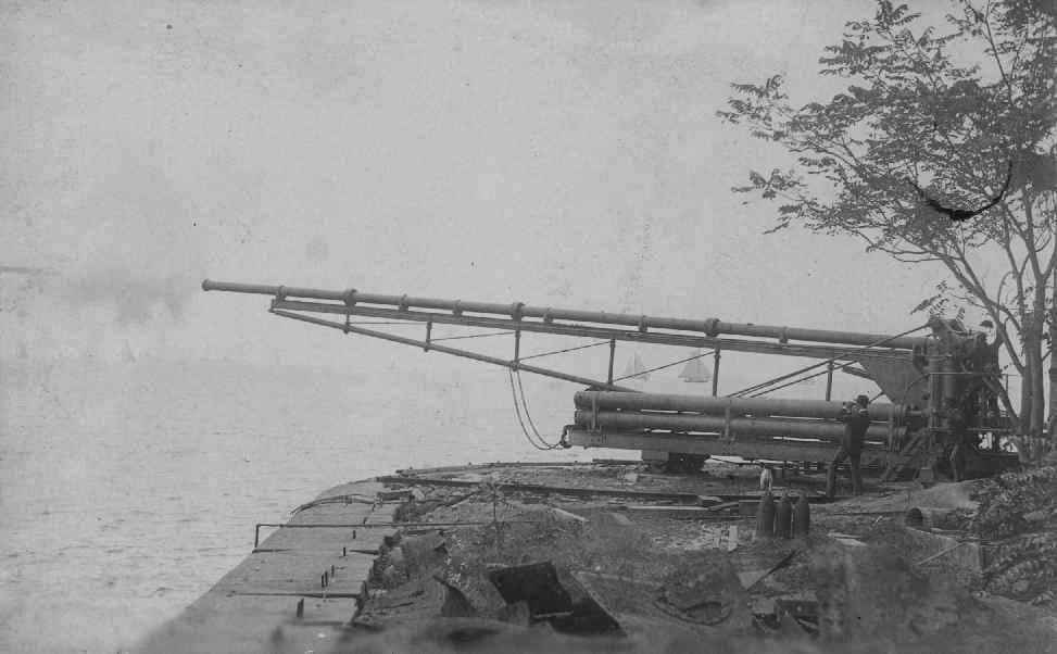
Above: Early 8-inch Zalinski gun on trials: 189?
|
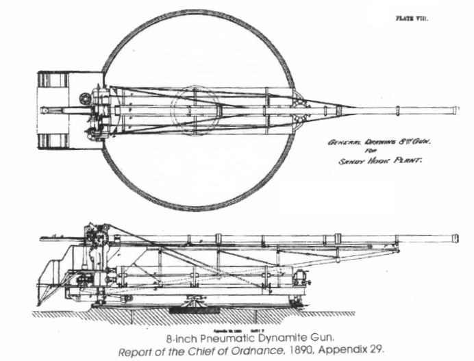 | Left: Early 8-inch Zalinski gun drawings: 1890
|
![]()
RAPIEFF COASTAL DEFENCE GUNS
Captain Rapieff was a former Russian artillery officer living in the US. He was the chief engineer of The Pneumatic Dynamite Gun Company of New York, formed to exploit pneumatic guns once Zalinski had proved their potential. Captain Rapieff does not have a Wikipedi page.
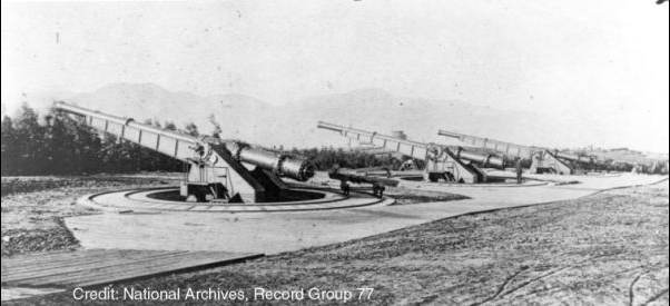 | Left: Three 15" Rapieff dynamite guns: 1894
|
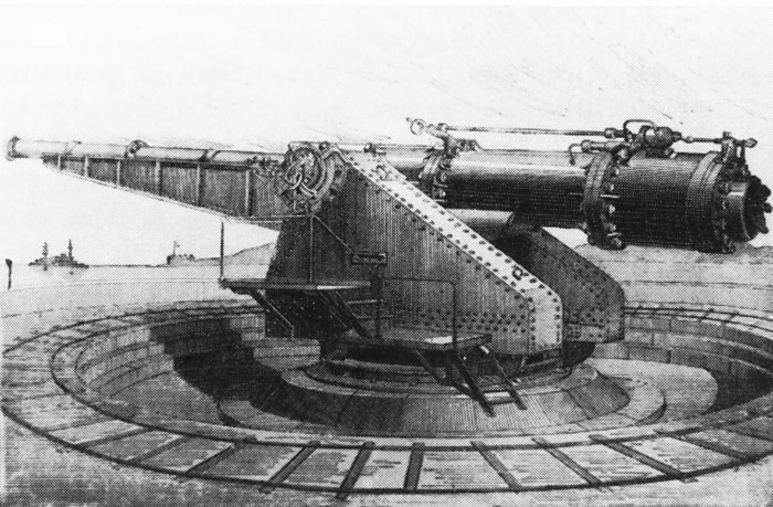 | Left: Rapieff coast defence gun: 189?
|
 | Left: Rapieff coast defence gun: 189?
|
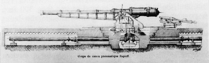
 | Left: Rapieff coast defence gun: 1894
|
 | Left: Rapieff coast defence gun: 1894
|
![]()
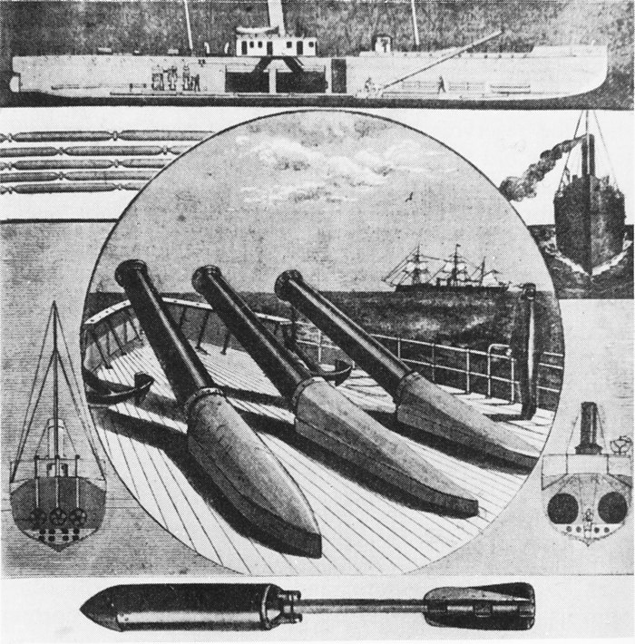
DYNAMITE GUNS AT SEA
The 239-ton steamer USS Vesuvius was built 1887-88 and commissioned in June 1890. She was fitted with three 15-inch Zalinski guns firing at a pressure of 1000 psi.
 | Left: USS Vesuvius: 1890
|
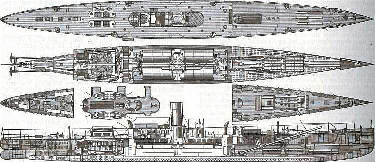 | Left: The Vesuvius plan and section: 1890
|
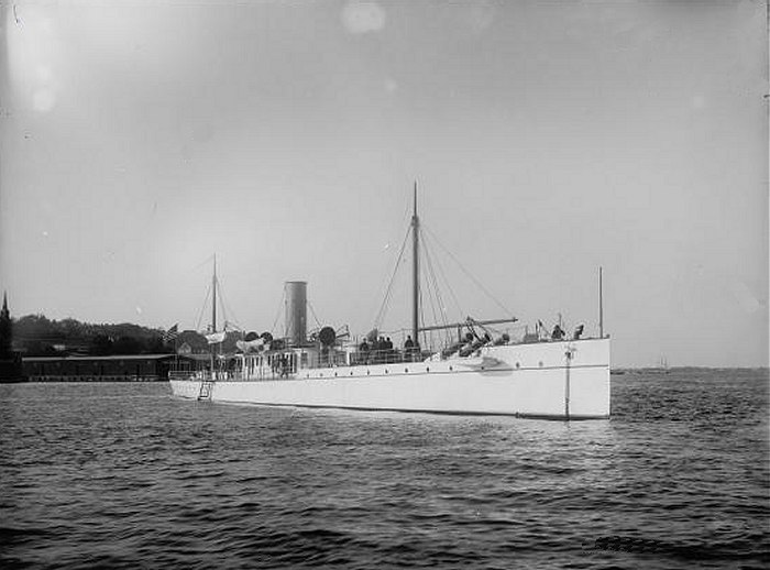 | Left: The Vesuvius 'dynamite gunboat': 1890
|
During the Naval Revolt of 1893-1894, Brazil called on Captain Zalinsky to install a single 15 inch pneumatic gun aboard the converted Brazilian Nictheroy (ex-El Cid) in 1893. This weapon was installed in an electrically powered open mounting that could be elevated, and trained through an arc of 300 degrees; a considerable improvement on the fixed guns of the Vesuvius. The crew for this weapon was one officer and 14 men. The Brazilian navy was at the time in a dire state, and their only option was to hire mercenaries. Flint, the American 'admiral' of an small and assorted fleet, recalled: "The only odd feature was that there was not a man aboard the ship who who had ever seen the (Brazilian) flag before, or who could speak the language of the country for which he was faring forth so gallantly to fight." Flint made no pretence of caring about Brazilian politics; this was just business.
 | Left: Rapieff pneumatic gun installation on the Brazilian cruiser Nictheroy: 1894
|
Quoting from a "Proceedings of the United States Naval Institute, 20, #72" article:
"A correspondent on board that vessel writing under date of March 15, 1894 says Captain Baker and the other officers speak in enthusiastic terms of the trial of the cruiser's famous dynamite gun; just before entering the harbor on the day of the surrender of the rebel forces, a shell was fired at Pai Island in the bay and all agree that the explosion was 'fine'." It was probably fortunate that the mutineers surrendered, as the pneumatic gun was apparently disabled by this first shot. The gun's commander was suspected of being a traitor and was disrated as a result. (Which sounds very strange- if he really was some sort of saboteur you would have though he'd be shot) The Nictheroy was disarmed and the pneumatic gun was then reportedly mounted as a coast defense weapon at Fort Sanata Cruz.
This account is rather puzzling because, as noted above, the crew of the Nictheroy were all US mercenaries, and not likely to be seduced by the rebel cause.
One of the first submarines, the USS Holland, built by John Holland with contributions from Zalinski, had a 8.4-in dynamite gun designed to fire "aerial torpedoes".
![]()
ZALINSKI GUNS IN ENGLAND: 1894?
I was much surprised to find a Zalinkski gun had been installed for trials in England. Here is an account by Penrose Fitzgerald, who took charge of Pembroke Dockyard on the 9th of February 1893, and spent two years there, being promoted to the rank of Rear-Admiral on the 20th of February 1895:
"Next year we had another Royal visitor. The Duke of Cambridge came down to inspect some troops, which were paraded for him in the dockyard. He expressed a wish to see the famous Zalinski gun fired. The Zalinski gun was a sort of gigantic pop-gun fired with compressed air. It was sunk into the ground in a trench, and, as well as I can remember, it could not be trained horizontally, though it admitted of some adjustment of elevation. It was more of a tube than a gun, and it hurled into the air (if it went off) a projectile which was more of an aerial torpedo than a shell, and the said projectile was fitted with a delayed-action fuze, which was intended to become operative a few seconds after the missile had struck the water. It was not necessary to hit an enemy's ship in order to destroy her, for if the missile exploded anywhere near her she would be blown to smithereens - at least, so said the inventor."
"The Zalinski gun was mounted at Dale, on the western shore of the entrance to Milford Haven, about nine miles from Pembroke Dock; and as the Duke had expressed a wish to see the gun fired, I took him and his staff down to Dale in the Dockyard tug Stormcock, and as we were to make a day of it, I provided them with lunch. I had been told that the Duke was fond of pork chops, so I made ample provision in that respect, and pork chops formed the principal item in my menu. My information was apparently correct, for the Duke polished off three or four pork chops and was in the best of humours, as also was the chief of the staff - the late Sir Redvers Buller, of South African renown."
"On our arrival at Dale, orders were given to fire the Zalinski gun and drop a projectile just outside the entrance; while the Stormcock, with the Duke and party on board, lay-to just inside to watch the effect; but after waiting along time and nothing happening, a signal came from the shore to say that the gun would not go off at present and there was no knowing when it would go off - if ever.
The Duke was very grumpy, used some quite uncomplimentary language about the Zalinski gun, and told me to take him home."
This is from the second volume of Penrose Fitzgerald's autobiography 'From Sail to Steam'. It appears that the year is 1893 or 1894.
More information on the Zalinksi gun in England surfaced in Coast Defences of Ebgland & Wales by Master-Gunner Ian Hogg. (David & Charles, 1974)According to Hogg, a 10-inch calibre Zalinski gun was given initial trials at Shoeburyness, then installed in Dale Fort at Milford Haven. Numerous trials were fired against a paddle-steamer borrowed from the Admiralty. The Ordnance Committee turned down the weapon as it disliked the complications of the air compression machinery, and because the performance was not as good as conventional guns. A good call.
It seems strange that the calibre reported is 10-inch, because the American guns appear to have all been 15-inch, apart from the 8-inch prototype.
![]()
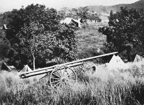
THE DUDLEY DYNAMITE GUN: 1898
 | Left: The Dudley dynamite gun: 1898
|
![]()
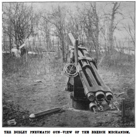
THE SIMS-DUDLEY DYNAMITE GUN: 1898
 | Left: The Sims-Dudley dynamite gun: 1898
|
 | Left: The Sims-Dudley dynamite gun: 1898
|
 | Left: The Sims-Dudley dynamite gun: 1898
|
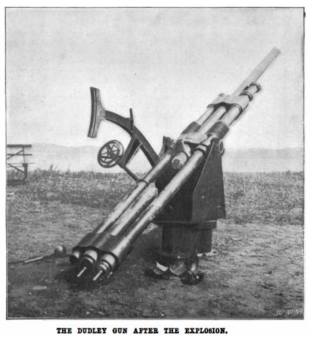 | Left: The Sims-Dudley dynamite gun explodes: 1896
|
 | Left: The Sims-Dudley dynamite gun: 1898
|
 | Left: The Sims-Dudley dynamite gun dismantled: 1898
|
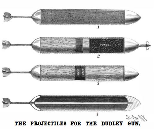 | Left: Projectiles for the Sims-Dudley dynamite gun: 1898
|
![]()
THE DORMOY-CHATEAU 50mm PNEUMATIC MORTAR
According to some sources this mortar was the 'ancestor' of the Brandt 60mm mortar shown below.
 | Left: Dormoy-Chateau 50mm pneumatic mortar
|
 | Left: Dormoy-Chateau 50mm pneumatic mortar
|
 | Left: Dormoy-Chateau 50mm projectile
|
![]()
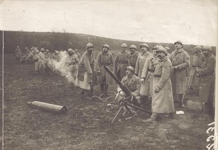
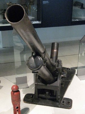
THE BRANDT 60mm PNEUMATIC MORTAR
The Brandt 60mm pneumatic mortar was invented by Edgar William Brandt, apparently in 1915. He has a Wikipedia page. In 1916, the French army placed an order for 3,000 of these mortars, plus 3 million shells, with Brandt's company. Brandt's father was a displaced person from Alsace after that province was grabbed by Germany in the Franco-Prussian war, which explains his germanic-sounding name.
 | Left: The Brandt 60mm pneumatic mortar: 1915
|
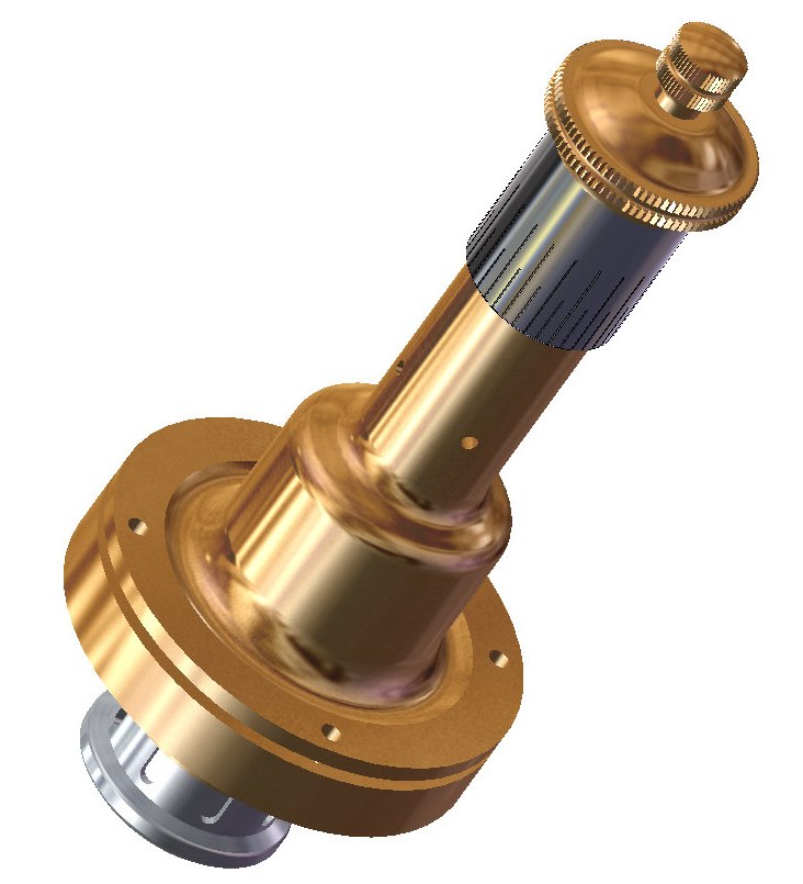
In a conventional gun, the larger diameter at the breech would indicate reinforcement to deal with the firing pressure. In this case it is actually a cylindrical air reservoir coaxial with the barrel. In a pneumatic gun it is essential to release a lot of air quickly behind the projectile, and letting it trickle to its destination through a narrow hose will not work. Here the reservoir was charged via the hose, but its entire contents were applied to the projectile almost instantly by the opening of a piston valve that gave free communication between the reservoir and barrel.
 | Left: Brandt 60mm mortar just after firing
|
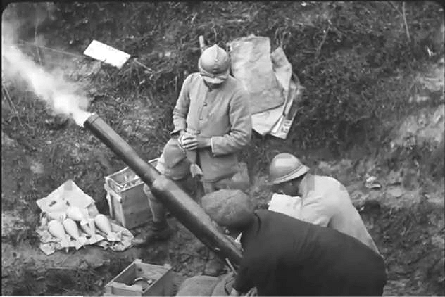 | Left: Brandt 60mm mortar just after firing
|
 | Left: The firing mechanism of the Brandt 60mm mortar
|
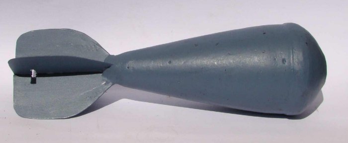 | Left: Brandt 60mm mortar projectile
|
The Brandt 60mm pneumatic mortar does not appear to have a Wikipedia page.
Brandt's company is now known as TDA and still makes mortars.
![]()
THE BOILEAU-DEBLADIS 86mm PNEUMATIC MORTAR
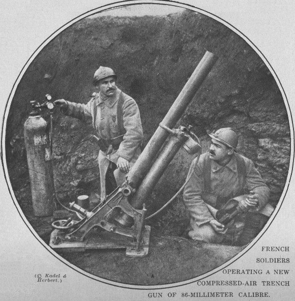 | Left: Boileau-Debladis 86mm pneumatic mortar
|
 | 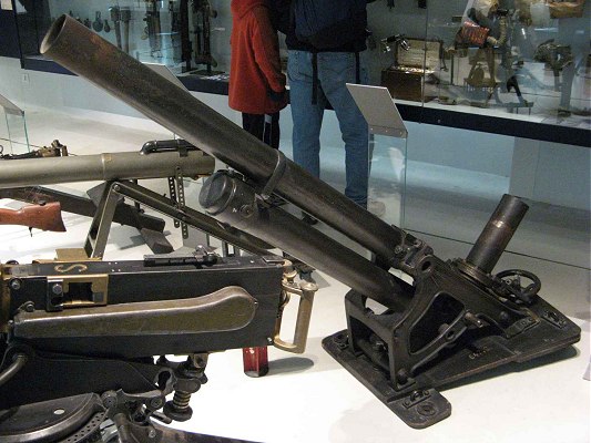 | Left: The Boileau-Debladis 86mm pneumatic mortar
|
The Aasen mortar was a 3.5-inch (88.9-mm) mortar, invented in France in 1915 by Nils Aasen, a Norwegian. The bolt action on top of the barrel fired a blank rifle round which produced gas pressure behind the projectile. It was adopted by Imperial Russia in 1915-1916, and was also used by the French, who called it the "Obusier Aasen de 86mm". According to "Les Canons de la Victoire 1914-1918" Vol.3 more than 2000 Aasen mortars were delivered to the French Army.
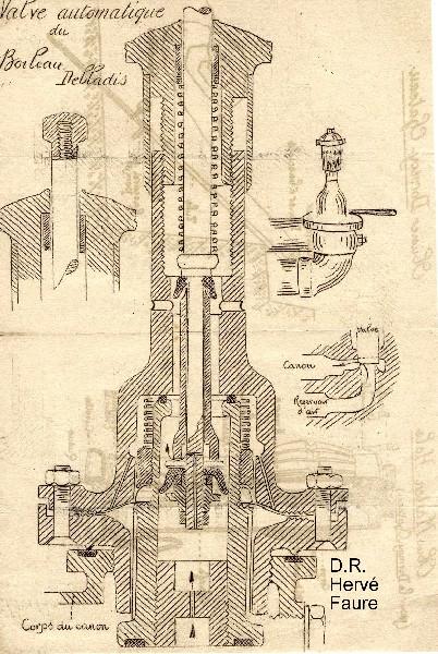 | Left: The valve of the Boileau-Debladis 86mm pneumatic mortar
|
 | Left: The Boileau-Debladis valve animated
|
 | Left: The exterior of the Boileau-Debladis valve, modelled by Bill Todd
|
The Boileau-Debladis pneumatic mortar does not appear to have a Wikipedia page.
![]()
THE 120mm BRANDT-LHUILLIER PNEUMATIC MORTAR
 | Left: 120mm Brandt-Lhuillier mortar
|
The 120mm Brandt-Lhuillier pneumatic mortar does not appear to have a Wikipedia page.
![]()
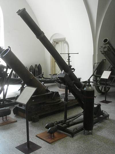
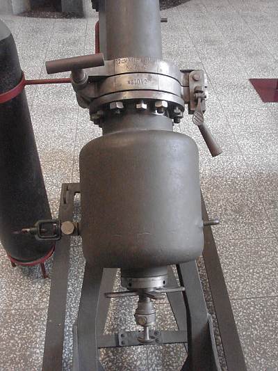
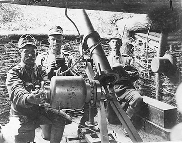
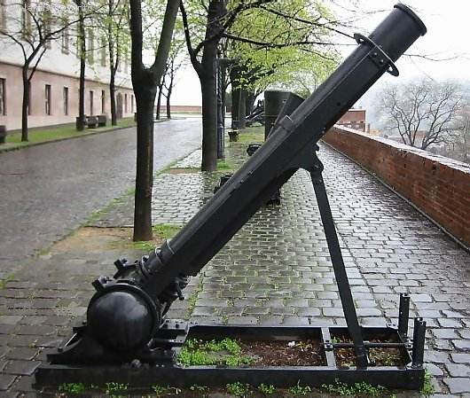
THE AUSTRIAN 8cm PNEUMATIC MORTAR
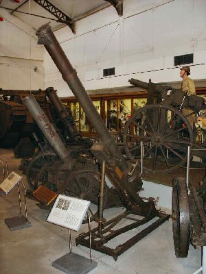
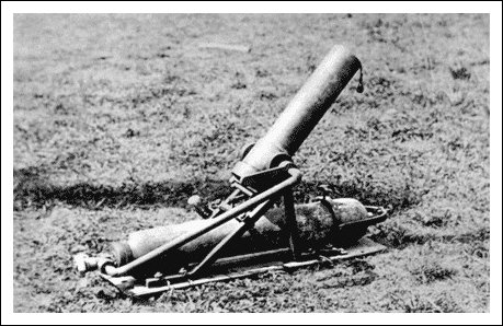 | Left: Austrian 8cm pneumatic mortar: 1915
|
Thedescription leaves much to be desired. It is not clear if the grooves are in the projectile or the barrel, and unclear how the depth of groove would affect the breaking stress of what was presumably some sort of set-screw that had to be screwed in for each round. This would not make for a rapid rate of fire. Presemably if you ran out of screws you were, well, screwed.
The use of this breaking-screw system seems a bit more logical when you consider that it appears to make a separate air reservoir unnecessary, which would much reduce the total weight of the weapon. In the picture it appears that the compressed-air cylinder is used as a stabilising weight instead.
The 86mm pneumatic mortar does not appear to have a Wikipedia page.
![]()
THE AUSTRIAN 10.5 cm PNEUMATIC MORTAR
The 10.5 cm Luftminenwerfer M15 was a medium mortar was developed by the German firm of Ehrhardt & Sehmer. it was muzzle-loading and had no recoil system. Each cylinder of compressed air was good for fifteen shots.
A batch of 25 mortars, 250 air cylinders and 10,000 bombs with fuses was ordered on 31 July 1915 for trials in the field, but Ehrhardt & Sehmer proved to be unable to deliver the mortar bombs, and these manufactured by the Army itself. A slightly improved model was offered by Ehrhardt & Sehmer at the end of March 1916, but it was rejected because of the lack of effectiveness of the ammunition, difficulty in procuring it, and its poor range. Ten trench mortar platoons, each with two mortars, were formed and deployed in February 1916, mainly to the Eastern Front.
Ehrhardt & Sehmer of Saarbr�cken made a large variety of machinery. After severe war damage in 1945 the company was still around for its 75th anniversary in 1951.
This pneumatic mortar has a Wikipedia page, but no picture of it has so far been found.
![]()
THE AUSTRIAN 12 cm PNEUMATIC MORTAR
 | Left: 12cm pneumatic mortar: 1916
|
 | Left: 12cm pneumatic mortar: 1916
|
 | Left: Austrian 12cm pneumatic mortar: 1915
|
![]()
THE AUSTRIAN 15 cm PNEUMATIC MORTAR
This pneumatic mortar was developed by Maschinenfabrik Esslingen for German use. Austria acquired a batch of five for testing. Evaluation in September 1915 was positive, and four of them were deployed in combat trials at the end of October 1915
No photograph or drawing has so far been unearthed, but it is thought the barrel had a full 360� of traverse on a base plate. One cylinder of compressed air was adequate for twelve discharges.
There was a Model II incorporating minor improvements suggested by both Austrian and German pioneer troops, which was evaluated at the end of 1915. Two hundred were ordered, but the mortar was rendered obsolete by the superior performance of the 12 cm Luftminenwerfer M 16 before production was finished, and the design was shelved.
The 15cm Luftminenwerfer M15 has its own Wikipedia page.
![]()
THE AUSTRIAN 20 cm PNEUMATIC MORTAR
 | Left: Austrian 20cm pneumatic mortar: 1916
|
![]()
THE HOLMAN PROJECTOR: 1940
The Holman Projector was a low-altitude anti-aircraft weapon used by the British Navy during the Second World War. It was defensive weapon for British merchant ships, against low-level attacks. Its range was short and accuracy poor but it could put up a large volume of fire which effectively deterred enemy pilots.
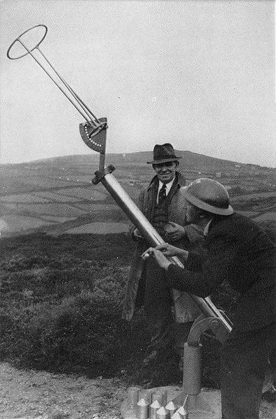 | Left: A Holman projector being prepared for initial trials on land: 1940
|
![]()
MODERN PNEUMATIC GUNS
Today we have the Light-Gas Gun as a research tool rather than a weapon. The NASA gun referred to there works very much like a Sims-Dudley, using gunpowder to compress hydrogen which spits a small projectile out of the barrel at up to 6000 m/s. Note that a bursting-disk is used to delay launch until the pressure has suitably built up.
On the other hand, the Combustion light-gas gun is intended as a weapon. The projectile is propelled by the combustion of hydrogen or methane, so it does not really count as a pneumatic weapon since the driving force is not stored pressure.
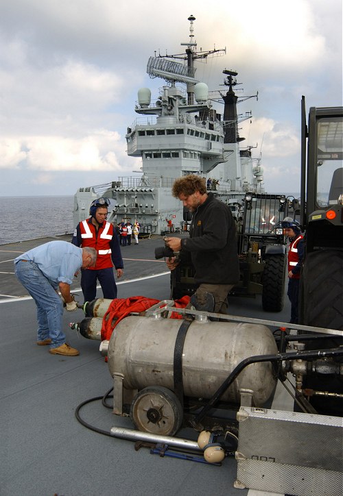 | Left: Preparing to launch a Jaguar off the deck of HMS Invincible: 2003
|
![]()

|