The title of this page has been changed to "Electro-Mechanical amplifiers", to distinguish them from mostly mechanical ones, such as the Frenophone, which can be found in the Mechanical Amplifiers gallery.
Page updated: 30 Jan 2022 New arc amplifier added 
  |
The year is 1900. Cost and attenuation are seriously limiting the growth of long-distance telephony, particularly in the USA.This needs a little explanation. You can always reduce the attenuation per mile of a telephone line by using thicker copper to reduce the resistance. Copper is however expensive, and there are limits to what is practical in this direction.
A Digression on Line Losses in Telephony.
To us, the obvious solution is to apply some amplification to boost signal strength; but it is long before the invention of the transistor, and even the valve (the vacuum tube to US readers) is still years away.
![]()
ELECTROMAGNETIC/CARBON AMPLIFIERS.
Mere lack of resource has never blocked human ingenuity, and there was a handy fact to exploit. Carbon microphones, as used universally in telephones until the mid-1960's, are not mere transducers that turn sound power into electrical power, but actually give a power gain of about a hundred times. The microphone is a variable resistance, made up of fine carbon granules, that controls the flow of current from a DC power supply; it does not merely convert acoustic energy into electricity. This power-amplification technology was the essential basis of the first practical telephone systems.
From this, it is but a short step to the concept of coupling a telephone receiver to a carbon microphone to make an amplifier, and several people took it. Within a few years of the original Bell invention, patents on this notion had been taken out by Edison, Houston, Lodge and Hughes, not to mention others less famous. By 1896, 27 patents for a mechanical-electrical amplifier- though it was then called a "repeater"- had been taken out.
Carbon microphones are not high-fidelity devices. Anyone who has used an old-fashioned telephone will recall that they would intermittently go low-gain or noisy, due to the granules packing, and a sharp rap of the handset against the wall was required to restore normal service. It was clear that the mechanical amplifier was far from perfect, but it was the only amplification option that looked practical.
 | Left: The basic operation of a mechanical amplifier is very simple.The electromagnet attracts the armature in response to the incoming signals. This varies the pressure on the carbon granules in the transmitting part, which varies their electrical resistance, and hence the current flowing in the output circuit. |
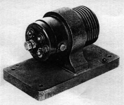 | Left: The first Shreeve mechanical amplifier: approx 1904.
In 1903 Herbert E Shreeve of the American Telephone & Telegraph Company (AT&T) was given the job of designing a practical mechanical amplifier. He discarded the microphone and earpiece diaphragms, and replaced them with a simple plunger that was driven by the receiving coil and pressed against the carbon granules of the transmitter.
One of the requirements of a practical amplifier was stability over time, which meant a solution to the problem of granule packing was needed. Shreeve found that this was due to thermal expansion caused by the heat liberated in the carbon chamber. This reduced the resistance, causing an increase in DC current but reduced audio output. This problem was controlled by designing the transmitter so that expansion of its parts did not increase the pressure on the carbon; and this led to the 1904 model below.
The first successful test was in 1904 on a circuit from Amesbury, Massachusetts to Boston. This model saw commercial use on a New York - Chicago circuit between August 1904 and February 1905. Note the cooling fins for the carbon microphone section at the right. Repeaters were originally used on non-loaded open-wire lines, with not more than one repeater in the circuit. (Bell 1944)
|
 | Left: The Shreeve amplifier patent: 1905
|
.jpg) | Left: Herbert E Shreeve: circa 1915
|
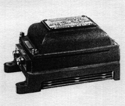 | Left: The Shreeve 1A amplifier.
The Shreeve 1A included a simple form of feedback control to control the mechanical pressure on the microphone element, and so the current through it. The current heated a zinc strip which withdrew the rear electrode to act against increases in this current; the thermal inertia prevented the signal being cancelled out as well as the long-term current trend. This was twenty years before the formal invention of negative feedback, though the principle had been in use for many years in the form of Watt governors. The cooling fins appear to be at the bottom. Horizontal fins are not efficient; they should be vertical. |
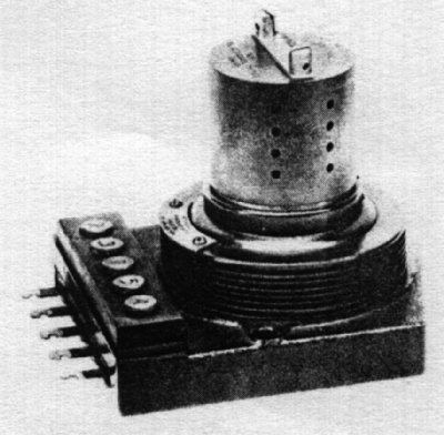 | Left: A cartridge type amplifier, Model 3A: 1914
|
 | Left: The internal construction of the Model 3A
|
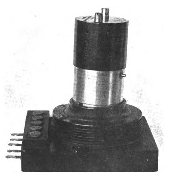 | Left: Another Model 3A repeater: 1919
|
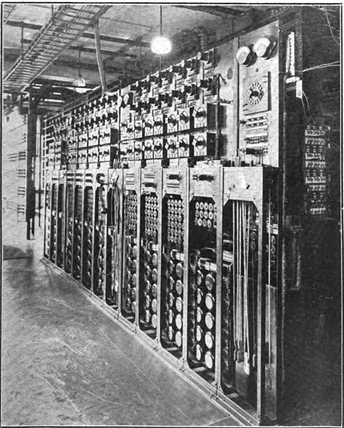 | Left: A bank of Model 3A repeaters: October 1919
|
![]()
ELECTROMAGNETIC/MERCURY-ARC AMPLIFIERS
I do appreciate that these are not strictly electromechanical amplifiers. But the history arc amplifiers is closely linked to them, so they're staying here.
THE HEWITT AMPLIFIER
There were other attempts to achieve amplification before the valve. Peter Cooper Hewitt, who introduced mercury-vapour discharge lamps in 1901, suggested an amplifier in which beams of mercury ions were deflected by electromagnetic coils. He was granted US patent 749,792 in 1904.The amplifier worked, but suffered badly from variable gain, noise, and distortion. Hewitt went on to introduce the very successful mercury-arc rectifier, which was widely used for heavy-current rectification until the 1970s.
 | Left: The Hewitt mercury-arc amplifier
|
![]()
THE ARNOLD AMPLIFIER
In 1912 Dr H D Arnold produced an improved amplifier on this principle; it had a good frequency response, but had such severe starting and maintenance difficulties it was unsuitable for unattended operation. It was used experimentally on the transcontinental circuit, but never commercially.
 | Left: The Arnold mercury-arc amplifier.
The arc thus moves between two subsiduary electrodes, in a way that is not too clear from this drawing, and the audio output is taken from the balanced to unbalanced transformer T2 to the earphone at lower left. |
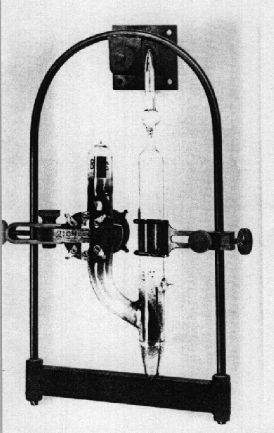 | Left: The Arnold mercury-arc amplifier
|
![]()
THE VON LIEBEN AMPLIFIER
Another possible amplifier investigated was the cathode-ray amplifier of Robert von Lieben; it proved to be no more promising. It controlled the flow of cathode rays rather than a mercury arc.
 | Left: The von Lieben amplifier
|
Dieckman & Clag (of Strasbourg) filed for a patent on a similar device in 1906; this used electrostatic rather than magnetic deflection of the beam. No further information has been found so far. Dieckman & Clag are unknown to Google.
![]()
EARLY VALVE AMPLIFIERS
Meanwhile, the vacuum tube as we know it was being created. Fleming produced a thermionic diode in 1904, and in 1907 a US Patent was granted to Lee de Forest for adding a control grid, to make the first triode. By October 1912 de Forest was demonstrating a valve audio amplifier to Bell officials. By October 1913 improved valves had been built and tested on commercial circuits between New York and Baltimore, and at the end of 1914 valve amplifiers were in use on the transcontinental circuit. It was clear that valves were the way ahead, and the mechanical amplifiers built for this service were placed on standby.
So, was that the end for this technology? Indeed not. Now read on...
![]()
THE S G BROWN ELECTROMAGNETIC AMPLIFERS
S G Brown Ltd, of London, were well-known makers of headphones. They manufactured several models of electromechanical amplifier, working as above with the input coils moving an armature connected to a carbon microphone. The microphone worked in push-pull; in other words one carbon capsule was compressed while the other was released, and the anti-phase outputs were combined in a transformer. What they called the "Microphone Bar Amplifier" was first manufactured during WW1 (1914-18) and was used by the British Army; after the war a large number were sold off as government surplus. I think 'Bar' is probably an acronym for 'Brown Audio Relay' but this is unconfirmed at present.
By the early 1920s, S G Brown were advertising their 'Crystavox' loudspeaker, which was an electromechanical amplifier combined with a horn loudspeaker in a single unit.
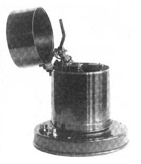 | Left: A Brown electromechanical amplifier: 1914
|
 | Left: Diagram of Brown electromechanical amplifier: 1914
|
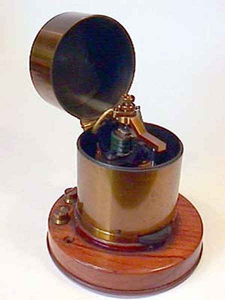 | Left: A Brown electromechanical amplifier: 1914
|
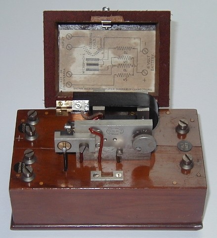 | Left: A Brown Type V electromechanical amplifier: about 1924
|
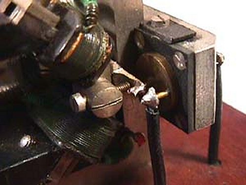 | Left: A Brown Type V electromechanical amplifier: about 1924
|
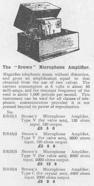 | Left: A contemporary advertisement for Brown amplifiers, showing the Four models were available. The one shown above is a R53/3 Type V.
Interestingly the amplifier is claimed to be "without distortion", which is quite untrue; distortion was high. The prices shown were a great deal of money for the time.
Rather strangely, the instrument is said to be suitable for all classes of communication, despite having a 1 kHz resonant frequency clearly chosen with CW (morse) in mind.
These two pictures are reproduced by kind permission of Lorne Clark, whose very fine website can be seen at earlywireless.com.
|
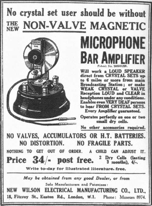 | Left: A 1927 advertisement from the New Wilson Company.
|
You can see a double Brown amplifier here. It is described as a 'crystal amplifier' but that means it was intended to amplify the output of a crystal radio set; crystals were not involved in the amplification. The power gain was said to be about 1000 times, implying a voltage gain of some 30 times, which sounds plausible. Each of the two amplifiers therefore had a voltage gain of about 5.5 times. There is an adjustment lever for each amplifier.
![]()
THE TANNOY POWER MICROPHONE.
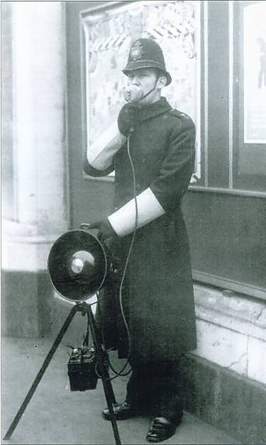 | Left: A policeman demonstrating the power microphone PA system in 1937.
|
![]()
ELECTROMAGNETIC/CARBON HEARING AIDS
As I said above, a carbon microphone in itself is an amplifier. Until miniature valves became available in the late 1930's, a valve hearing-aid was not very practical. Early valves were rather large (imagine a hearing-aid constructed with octal valves) and battery drain was high for the filaments. There were a few large hearing aids with valves, but the majority of the electrical hearing aids sold between 1900 and 1938 were electromagnetic/carbon.
 | Left: circuit of the Western Electric No 38A Audiphone hearing-aid.
The rheostat is presumably a gain control, and appears to alter both the microphone energising current and the amplifier energising current. This no doubt saves battery power when the full gain is not required.
The circuit shows three cells in the battery. If this may be taken literally the operating voltage was about 4.5V
|
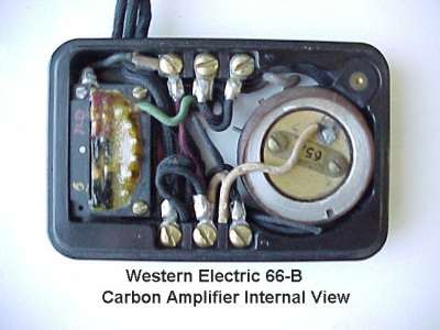 | Left: internals of the Western Electric No 66B hearing-aid. This appears to have the same circuit as above. The rheostat is on the left, and the microphone, earphone and battery are all external to this little box.Mr Hugh Hetherington (who kindly supplied this image) tells me that the hearing-aid carbon microphone employed a carbon ball technique rather than the carbon dust used in telephone transmitters; these apparently gave more amplification than the carbon dust transmitters, but were never used in telephones. |
ELECTROMECHANICAL AMPLIFIERS IN CABLE BROADCASTING.
This topic was originally an external link to a very informative webpage. Sadly, this link seems to have died, so I give a much condensed account below. I have been unable to locate the original site builders- if anyone feels I have purloined information, please let me know.
In early 1912 several businessmen from New York were traveling in Austria-Hungary and while in Budapest, they were surprised to learn that they could listen to concerts or lectures without leaving their rooms. Budapest had an early cable distribution system that drove headphones.
These gentleman saw business potential in this, and formed the New Jersey Telephone Herald Company. It was decided to install the system in Newark, New Jersey, with the idea that if it was successful there, it would be introduced in New York. Wires were leased from the telephone company, installation was started early in the Spring of 1912 ,and regular programs were being broadcast by July. The programs were produced in a suite of rooms very similiar to a present day studio for a radio broadcast station, with acoustic treatment on the walls and Erickson microphones.
What is not currently clear is how the signal from the microphones was amplified so it could drive hundreds of headphones across a city.
For the first two or three months the subscription department was swamped with orders for installations, and within the first three months there were about 5,000 subscribers. The service cost $1.50 a month. However, as with everything else, people soon tired of their new toy, mainly because loudspeaker reception was not available, although the signals that were received were very clear and of excellent head-phone volume.
The management of the company realized where the difficulty lay and Mr. Rainbault and his chief engineer, Mr. J. L. Spence, worked on the perfection of a "mechanical amplifier". No details are currently known but this probably worked on the same electromagnetic/carbon scheme as the telephone repeaters above. However, the results obtained were far from satisfactory, so in December of the same year it was decided not to fight any longer against such odds. The New Jersey Telephone Herald Co. was closed and the headsets removed from the homes of Newark. There had been an outlay of over $200,000.
Thus electromechanical amplifiers once more proved unequal to the task of amplification. Radio broadcasting in the USA did not begin until 1916.
I would be very glad to hear from anyone who has any more information on these remarkable byways of technology.
Acknowledgement: This article draws heavily on the book "Engineering and Science in the Bell System". All speculation is mine.

|