The Limelightand other illuminants |
Gallery opened 9 Apr 2025 |


![]()
Limelight is a now obsolete method of generating an intense white light. It saw quite wide use in theatres and for slide-projection, until replaced by electric arc lights. The name however lives on, as someone in the public eye is said to be in the limelight. Very few people know what that meant.
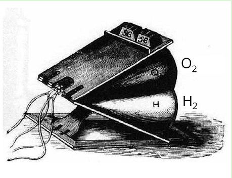
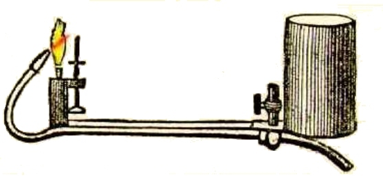
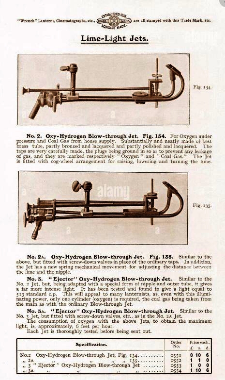 | Left: Oxygen-gas burners for creating limeight: 18??
|
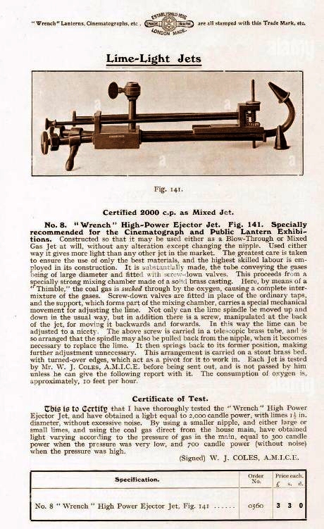 | Left: Oxygen-gas burners for creating limeight: 18??
| ||||
‘Three photographic artists, Messrs. Freeman, Cornock, and Stone, were engaged in making oxygen on Mr Freeman’s premises in Hindley street, when a loud report was heard, a cry of fire was raised, the fire-bell was rung, the engines brought to the spot, and a general alarm was raised in the city. On investigating the cause of the explosion, it was found that the gentlemen named had placed upon the fire a retort filled with gas-making materials. The retort was scarcely heated, when it exploded with a loud report. The room with its furnishings was almost entirely destroyed; Mr Freeman was seriously injured, and lost the sight of an eye; and Mr Cornock subsequently experienced a long illness, brought on by inhaling the suffocating gases which the explosion produced. The manganese in this case had been procured from a respectable chemist in Adelaide.’ | |||||
‘A week or two ago [June 1866] Mr Cornock, a little daunted, but not intimidated by his previous experience, procured from the same chemist a second supply of manganese, with the usual proportion of chlorate of potash. Having been duly assured of the purity of the materials he commenced, in conjunction with Mr Dobbie of Gawler Place, a second gas-making experiment. As in the previous case great care was taken in the adjustment of the apparatus, but the fire had scarcely obtained access to the retort when the whole thing again violently exploded, nearly destroying the premises, the operators having a narrow escape with their lives.’ | |||||
"The employment of oxygen for limelight and other purposes has increased enormously since the commercial introduction of the Brin method, by which the gas is separated from atmospheric air by a now well-known chemical process.The gas so obtained is practically pure, analysis showing that as now supplied by the Brin companies it contains on an average 95 per cent. of oxygen, the remaining five per cent consisting of inert nitrogen." |
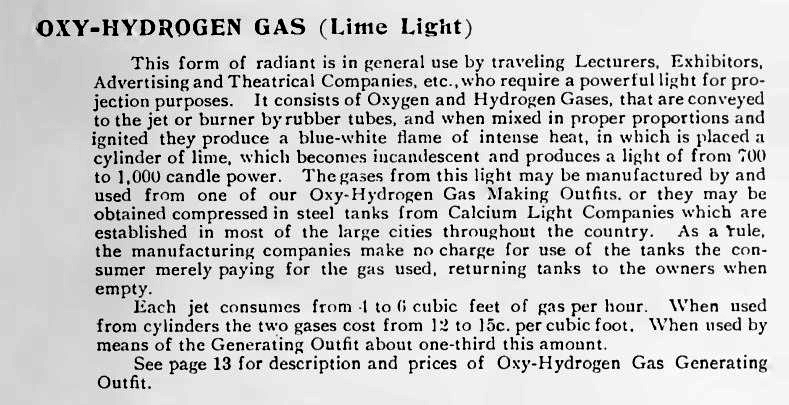 | Left: A Word on how to supply the gases to the limelight: 1880s
|
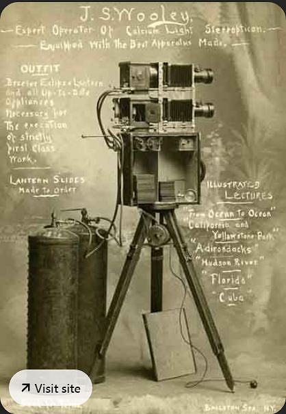 | Left: A Bessler Stereopticon Projector owned by J S Wooley: 1894
|
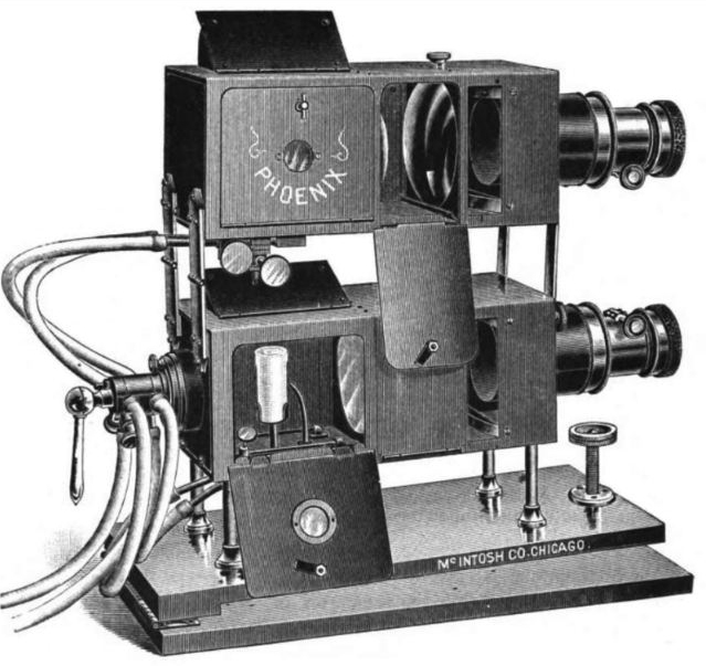 | Left: A Phoenix Stereopticon: 18??
|
 | Left: Limelight bellows for storing hydrogen and oxygen
|
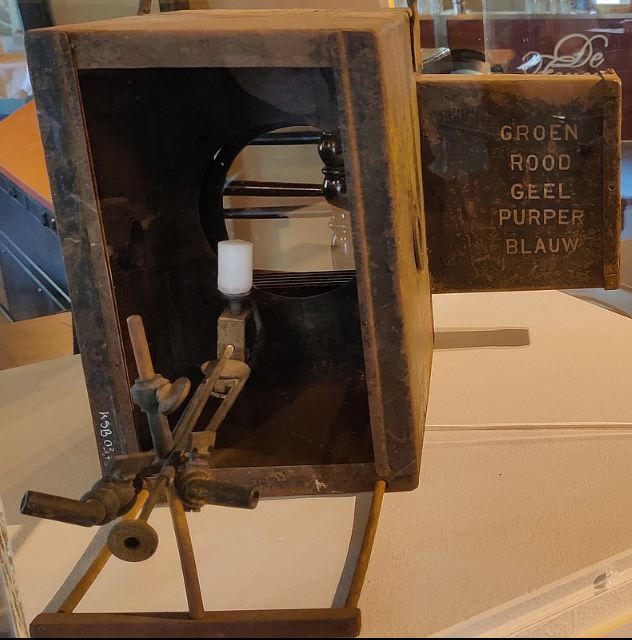 | Left: Limelight apparatus with sliding colour filters
|
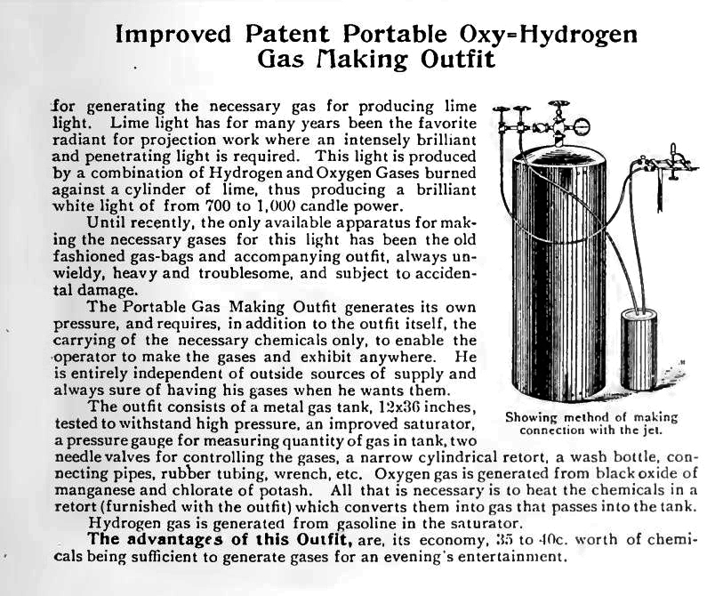 | Left: Oxygen and hydrogen generator
|
 | Left: Oxygen and hydrogen generator
|
![]()
Before the limelight was introduced, there were other ways of showing magic lantern slides.
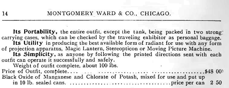
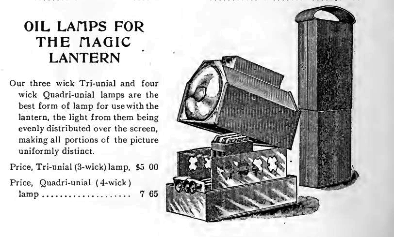
OIL LAMPS
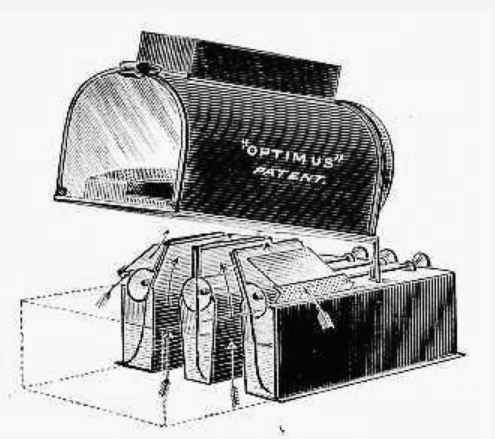 | Left: A three-wick oil-lamp for magic lantern use
|
 | Left: Another three-wick oil-lamp for magic lantern use
|
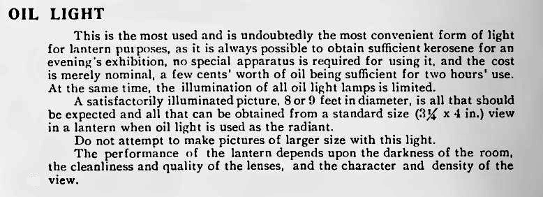 | Left: Helpful advice on using kerosene as an illuminant
|
![]()
THE OXY-CALCIUM LAMP
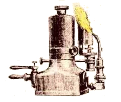
 | Left: An oxy-calcium lamp
|
![]()
THE OXY-ETHER LIMELIGHT
 | Left: An Oxy-Ether saturator and burner
| ||
"Personally, I prefer the original form of saturator introduced into this country from America, which consists of two parallel brass barrels, within which are stuffed close-fitting rolls of absorbent flannel rolled round a spiral coil of wire to preserve an open gas passage." |
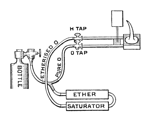 | Left: A diagram of an Oxy-Ether system
| ||
"To Light Up with Ethoxo. See that H jet tap is open and 0 jet tap closed.Turn cylinder key, then give regulator a few turns.When you smell ether, take off chimney of lantern,and after waiting a few seconds apply a light. Don't be alarmed at a big flame. Turn it down by the regulator till there is an inverted cone of burning vapour of about two and a half inches in length. Warm lime as usual, then gradually turn on 0 tap at the jet, and adjust just as you would with a blow-through or a mixed jet." |
![]()
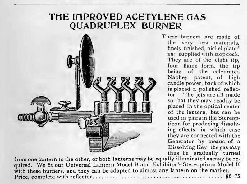
THE ACETYLENE LIGHT
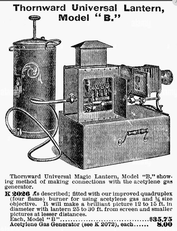 | Left: An Acetylene magic lantern and gas generator
|
 | Left: An Acetylene magic lantern gas generator
|
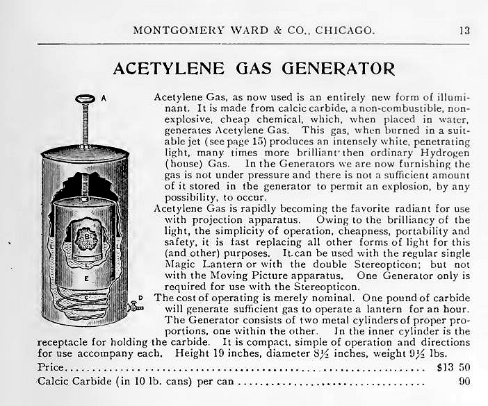 | Left: An Acetylene magic lantern gas generator
|
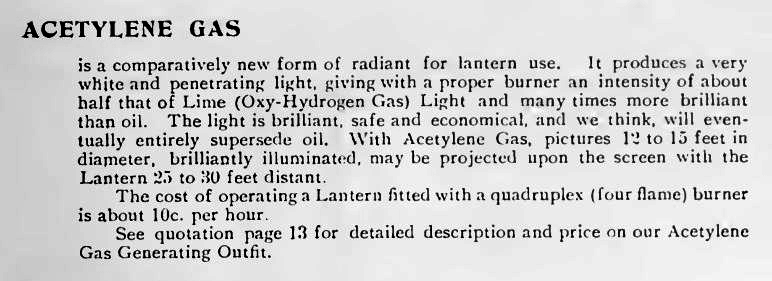 | Left: Helpful advice on using acetylene as an illuminant
|
![]()
THE ELECTRIC ARC LIGHT
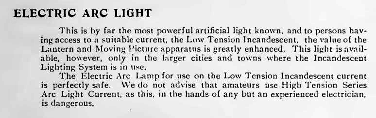 | Left: Notss on the electric arc light
Arc lamps have a Wikipedia page. |
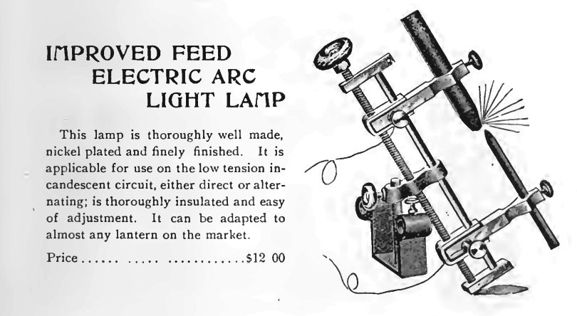 | Left: An electric arc light
|

|