Updated: 31 July 2004
This remarkable patent was drawn to my attention by Anthony Lealand.


This remarkable patent was drawn to my attention by Anthony Lealand.


The Fluidic Gramophone. |
Updated: 31 July 2004
This remarkable patent was drawn to my attention by Anthony Lealand.
 
|
In a conventional record-playing system, the mechanical vibrations of the stylus are converted to electrical signals. These are amplified and processed in the electrical domain, and are then converted to mechanical movements of a loudspeaker coil, and finally to pressure fluctuations in the air. The number of conversions from one domain to another is important, because each one introduces a significant loss of fidelity. We have just made three.
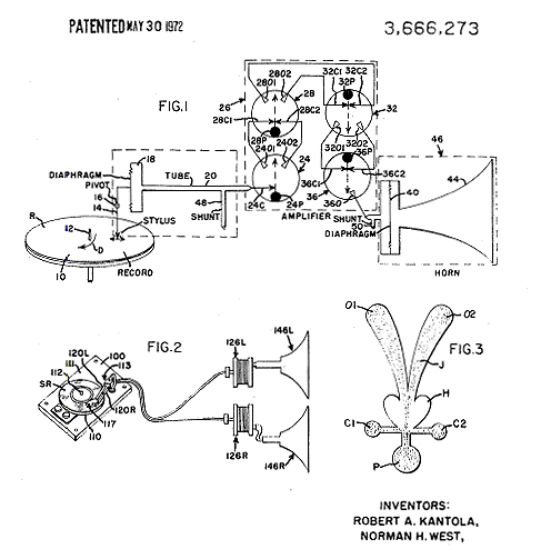
The fluidic gramophone offers the apparent simplicity of turning mechanical vibrations from the stylus into sound, and amplifying it directly by fluidic amplifiers before applying it to a horn. The simplicity is more apparent than real. Now we have a conversion from mechanical stylus vibration to air-pressure fluctuations, which appears to be the only one required; this is however not so. Close examination of Fig shows that there is a diaphragm in the throat of the output horn, so pressure fluctuations are converted back to mechanical vibrations, and then to air pressure variations again, no doubt for good reasons. This is three domain conversions again.
Another drawback is that the fluidic amplifier system here requires a source of compressed air at about 1psi. This must be very clean; if it is not totally free of dust and oil the fine air-passages will become blocked. Making a silent air compressor is inherently not an easy proposition; if it has to be cheap as well the difficulties are much greater.
 | Left: Diagrams from the Fluidic Gramophone Patent.
|
At least one prototype was built, but that was it. Given the need for an air compressor and careful filtering, it seems surprising that the advantage quoted for this system was economy.
The astute observer will also have noted that this design has no provision for a volume control, or bass and treble adjustment.
  
|